Suspension girder type forepoling bar device
A front-exploring beam and cantilever-beam type technology is applied to the roof beam supporting the mine roof, mining equipment, earth square drilling and mining, etc. It can solve the problems of uneconomical, unsafe, waste of manpower and material resources, etc., and achieves convenient and fast installation and high performance. Safe and reliable effect
- Summary
- Abstract
- Description
- Claims
- Application Information
AI Technical Summary
Problems solved by technology
Method used
Image

Examples
Embodiment Construction
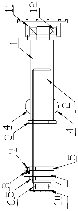
[0010] A cantilever-type front probe beam device, characterized in that it includes a fixed splint, a locking bolt, a nut, an I-beam top beam, a front probe beam, pins, a fixing hole and an adjustment hole, and two clamping slots for the fixed splint The lower edge of the I-beam top beam is fixed on the I-beam top beam by locking bolts and nuts. The front probe beam passes through the inner groove of the fixed splint, and passes through the adjustment hole on the front probe beam and the fixing hole on the fixed splint. Cooperate, and fix the probe beam through pins.
[0011] Uniform adjustment holes are arranged on the probe beam of the present invention.
[0012] The working principle of the present invention is as follows: the present invention utilizes the groove of the fixed splint to be stuck on the lower edge of the top beam bracket, and is firmly fixed on the top beam by locking bolts, and the front probe beam is fixed on the I-beam top beam to fix the splint device 1...
PUM
 Abstract
Description
Claims
Application Information
 - R&D
- Intellectual Property
- Life Sciences
- Materials
- Tech Scout
- Unparalleled Data Quality
- Higher Quality Content
- 60% Fewer Hallucinations
Browse by: Latest US Patents, China's latest patents, Technical Efficacy Thesaurus, Application Domain, Technology Topic, Popular Technical Reports.
© 2025 PatSnap. All rights reserved.Legal|Privacy policy|Modern Slavery Act Transparency Statement|Sitemap|About US| Contact US: help@patsnap.com