Al technical title is built by PatSnap Al team. It summarizes the technical point description of the patent document.
A technology of aviation obstruction lights and aircraft, which is applied in the field of aircraft aviation obstruction lights, can solve the problems of waste, scrapping of aviation obstruction lights, inconvenient replacement of aviation obstruction lights, etc., and achieve the effect of reducing friction and convenient use
Active Publication Date: 2019-12-10
深圳帝显高端制造方案解决有限公司
View PDF5 Cites 1 Cited by
Summary
Abstract
Description
Claims
Application Information
AI Technical Summary
This helps you quickly interpret patents by identifying the three key elements:
Problems solved by technology
Method used
Benefits of technology
Problems solved by technology
[0003] Aviation obstruction lights are mostly installed on the outside of the roof, and most of them are relatively dangerous places, so the replacement of aviation obstruction lights is very inconvenient, and the workers need to take great risks to replace the broken aviation obstruction lights, and The replacement aviation obstruction lights need to be scrapped as a whole, which also caused great waste
Method used
Image
Click on the blue label to locate the original text in one second.
Reading with bidirectional positioning of images and text.
Examples
Embodiment approach
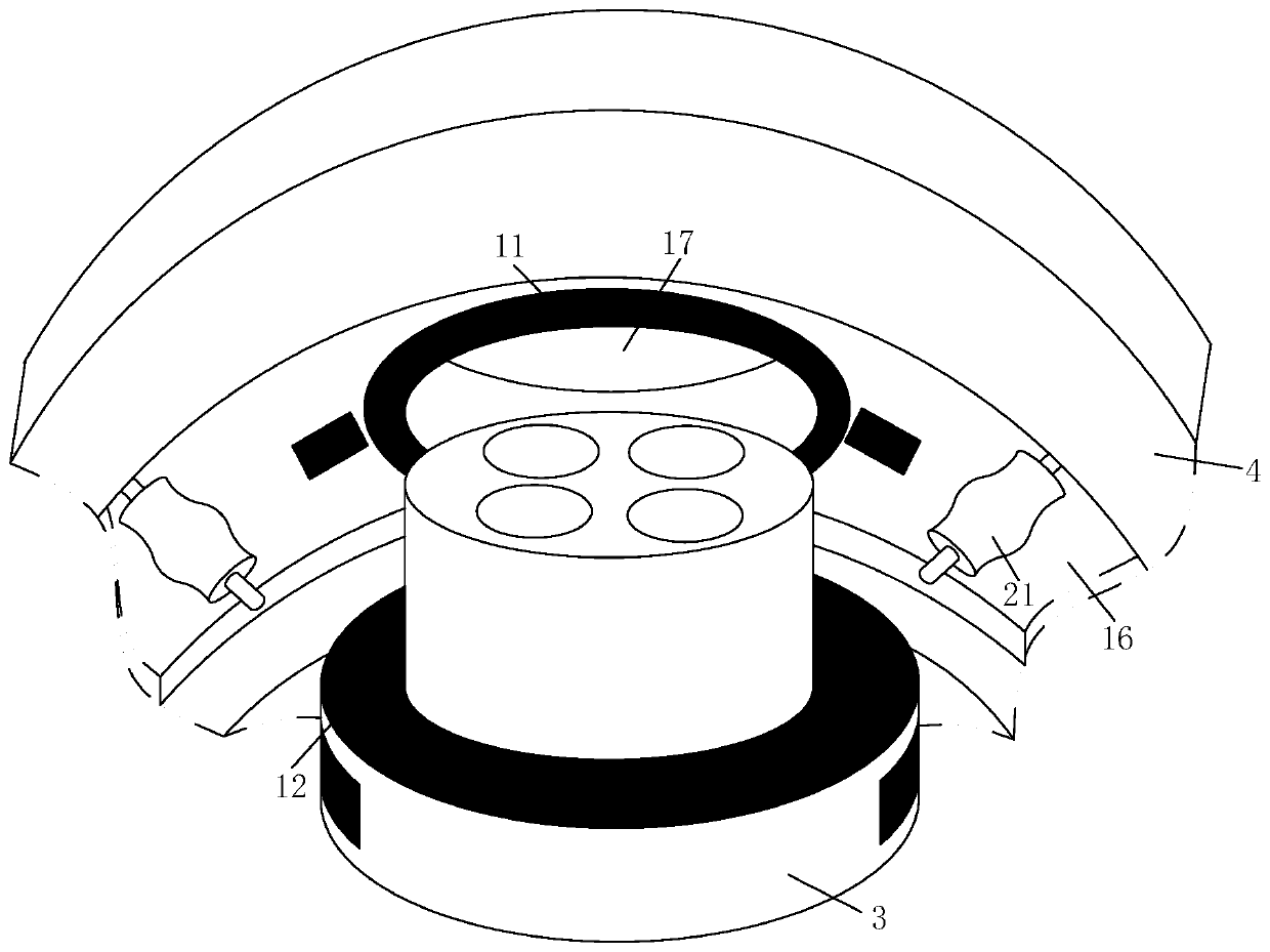
[0024] As an embodiment of the present invention, the top of the support column lower shell 9 base is fixedly connected with a fixed cylinder 18, when the LED bulb module 3 is located between the support column upper shell 8 and the bulb chute 16 under the action of the support spring 10 When the height of the top of the fixing tube 18 is higher than the bottom of the LED bulb module 3, when the LED bulb module 3 is located inside the bulb hole 17 under the action of the support spring 10, the height of the top of the fixing tube 18 is lower than that of the LED bulb module 3 bottom end. During work, when the turntable 7 rotates, the LED bulb module 3 above the support column upper shell 8 is driven to rotate together by the support column upper shell 8, the support column lower shell 9 and the support spring 10 on the turntable 7, if the support column upper shell If the frictional force between the upper part of 8 and the LED bulb module 3 is not enough, the LED bulb module ...
PUM
Abstract
The invention belongs to the technical field of aviation signal lamps, and particularly relates to an aircraft obstruction beacon. The aircraft obstruction beacon comprises a lampshade, an element boxand an LED bulb module, and also comprises an upper cover, a lower cover, a motor, a turn plate, a support pillar upper shell, a support pillar lower shell, a support spring, an LED lamp electrode upper plate, an LED lamp electrode lower plate, a motor remote control box, an upper motor fixing hole, a lower motor fixing hole, and a bulb sliding slot and a bulb hole formed on the inner side of thetop of the upper cover, wherein the bulb hole is formed in the upper cover, and the bottom end of the bulb hole is positioned in the bulb sliding slot; the element box is installed on the top of thebulb hole, a through hole is formed in the middle part of the element box, and the through hole is corresponding to the bulb hole; the lampshade is fixedly connected with the top of the upper cover, the lampshade is connected with the outer part of the element box in a sleeving manner, and the lampshade is positioned on the element box. According to the aircraft obstruction beacon, a plurality ofstandby bulbs are arranged to be stored at the bottom of the aircraft obstruction beacon in the way of the turn plate; when one LED bulb module is failed, the bulb is changed in a remote control manner; and the aircraft obstruction beacon is convenient to use and safer.
Description
technical field [0001] The invention belongs to the technical field of aviation signal lamps, in particular to an aircraft aviation obstruction light. Background technique [0002] With the development of society, there are more and more aviation vehicles, and more and more aircraft are used. Therefore, in order to avoid the occurrence of aircraft flight accidents, high-rise buildings will be equipped with aircraft aviation obstruction lights on the top. Obstruction lights show the outline of buildings to the pilot so that the plane does not collide with tall buildings. [0003] Aviation obstruction lights are mostly installed on the outside of the roof, and most of them are relatively dangerous places, so the replacement of aviation obstruction lights is very inconvenient, and the workers need to take great risks to replace the broken aviation obstruction lights, and The replacement aviation obstruction light needs to be scrapped as a whole, which also causes great waste. ...
Claims
Application Information
Patent Timeline
Application Date:The date an application was filed.
Publication Date:The date a patent or application was officially published.
First Publication Date:The earliest publication date of a patent with the same application number.
Issue Date:Publication date of the patent grant document.
PCT Entry Date:The Entry date of PCT National Phase.
Estimated Expiry Date:The statutory expiry date of a patent right according to the Patent Law, and it is the longest term of protection that the patent right can achieve without the termination of the patent right due to other reasons(Term extension factor has been taken into account ).
Invalid Date:Actual expiry date is based on effective date or publication date of legal transaction data of invalid patent.