LED lamp bead with reflection cup

A technology of LED lamp beads and reflector cups, which is applied in the direction of electrical components, circuits, semiconductor devices, etc., can solve the problems of accelerated aging of LED chips 02, low light efficiency of LED lamp beads, and high temperature of LED lamp beads, so as to reduce temperature and increase Heat sink and heat dissipation area, the effect of improving the light output rate

Pending Publication Date: 2019-12-10
江门江雷光电科技有限公司
0 Cites 0 Cited by

AI-Extracted Technical Summary

Problems solved by technology

Because the cup and bowl 04 are made of plastic with poor reflective properties, the light emitted by the LED chip 02 is difficult to reflect when it hits the inner wall of the cup and bowl 04, resulting in low light efficiency from the LED ...

Method used

Because the present invention is on the basis of original positive and negative electrode pads 5a/5b, forms the reflective portion 51 that extends along the side wall 42 of cup bowl 4 and is attached to the side wall 42 by metal sheet conjoined bending, The light irradiated by the LED chip 2 to the inner wall 42 of the ...

Abstract

The invention discloses an LED lamp bead with a reflection cup, which comprises a cup bowl, wherein the cup bowl is internally provided with a bottom wall and a side wall, the bottom wall in the cup bowl is provided with positive and negative electrode bonding pads, an LED chip is arranged in the cup bowl, the positive electrode and the negative electrode of the LED chip are electrically connectedwith the positive electrode bonding pad and the negative electrode bonding pad respectively, the positive electrode bonding pad and/or the negative electrode bonding pad are/is provided with a lightreflecting part extending to the side wall of the cup bowl, the light reflecting part is of a connected structure with the positive electrode bonding pad and/or the negative electrode bonding pad, andat least the surface of the light reflecting part is made of a light reflecting material. Due to the fact that the light reflecting part which extends along the side wall of the cup bowl and is attached to the side wall of the cup bowl is formed by integrally bending a plate, light irradiated to the inner wall of the cup bowl by the LED chip can be reflected by the light reflecting part, the heatsink area and the heat dissipation area are increased, the temperature of the LED lamp bead is reduced, and the service life of the LED lamp bead is prolonged more effectively.

Application Domain

Semiconductor devices

Technology Topic

EngineeringLED lamp +1

Image

  • LED lamp bead with reflection cup
  • LED lamp bead with reflection cup
  • LED lamp bead with reflection cup

Examples

  • Experimental program(1)

Example Embodiment

[0010] In order to further understand the features, technical means, specific objectives and functions of the present invention, the present invention will be described in further detail below with reference to the accompanying drawings and specific embodiments.
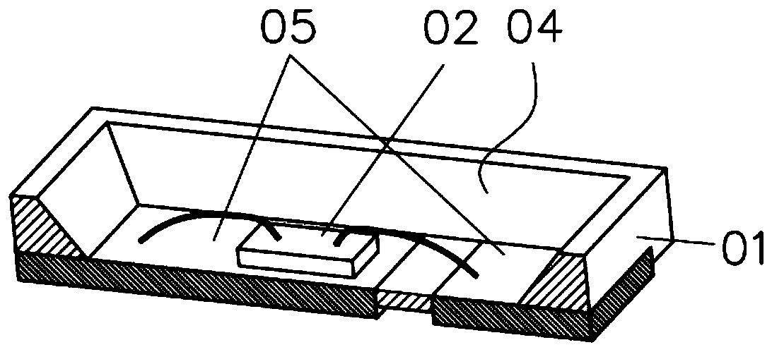
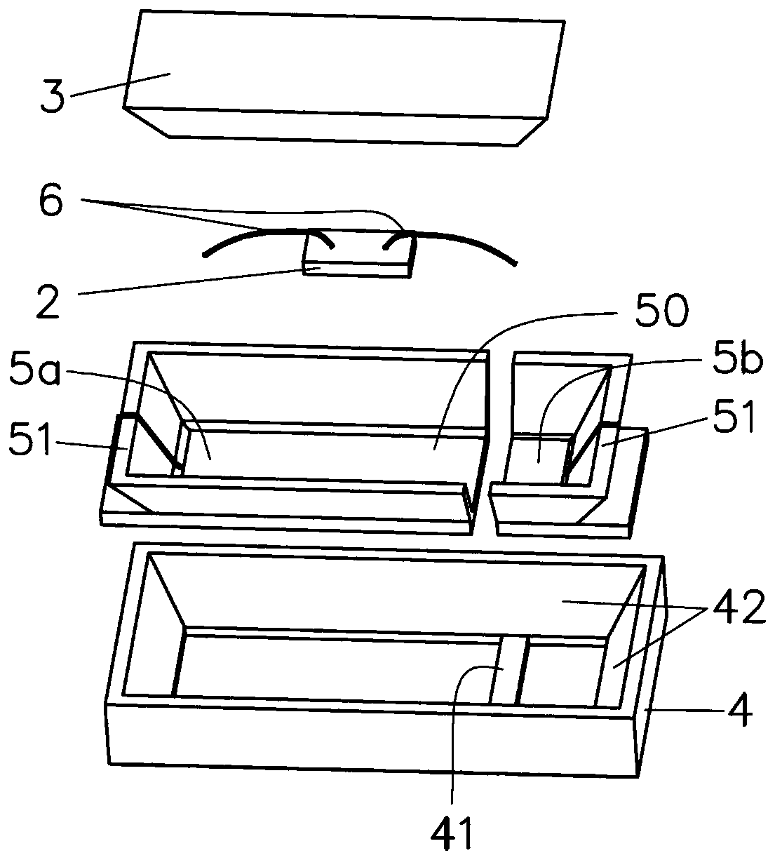
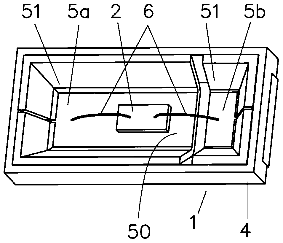
[0011] reference figure 2 , image 3 with Figure 4. An LED lamp bead with a reflective cup includes a bracket 1, an LED chip 2 mounted in the bracket 1, and a resin 3 covering the LED chip 2. The bracket 1 includes an injection-molded cup and bowl 4 and positive and negative electrode pads 5a/5b arranged in the cup and bowl 4. The bowl 4 includes a bottom wall 41, and a side wall 42 in a flared shape is enclosed around the bottom wall 41. A reflective part 51 extending along the side wall 42 and attached to the side wall 42 is provided on either or one of the positive and negative electrode pads 5a/5b. When one of the positive and negative electrode pads 5a/5b is provided with a reflective portion 51, the reflective portion 51 constitutes a half-horn-shaped reflector cup 50 structure; when both the positive and negative electrode pads 5a/5b are provided with reflective portions 51, The two reflective parts 51 are combined to form a complete horn-shaped reflective cup 50 structure. In order to simplify the manufacturing process, the positive and negative electrode pads 5a/5b and the reflective portion 51 can be continuously stamped or bent into a conjoined structure from metal plates with reflective effects. Of course, the positive and negative electrode pads 5a/5b and the light-reflecting portion 51 can also be made of other conductive materials, but at least the surface has a light-reflecting effect. Specifically, the surface can be realized by coating materials or electroplating. The LED chip 2 is fixed on the positive electrode pad 5 a or the bottom wall 41 in the cup 4 with resin, and the best position is the center of the reflector cup 50. The positive and negative electrodes of the LED chip 2 are electrically connected to the positive and negative electrode pads 5a/5b through welding metal wires 6 respectively. The present invention can be applied to white LED lamp beads and color LED lamp beads. When the LED lamp beads are white LED lamp beads, the LED chip 2 is a single or multiple blue LED chips, and the resin 3 is doped There is yellow phosphor; when the LED lamp beads are colored LED lamp beads, the LED chip 2 may include multiple LED chips 2 of different colors.
[0012] Since the present invention is based on the original positive and negative electrode pads 5a/5b, the reflective part 51 extending along the side wall 42 of the cup 4 and attached to the side wall 42 is formed by bending the metal sheet together, and the LED chip 2 The light irradiated to the inner wall 42 of the bowl 4 can be reflected by the reflective part 51, which increases the light extraction rate of the LED lamp beads, increases the heat sink and heat dissipation area, and reduces the temperature of the LED lamp beads without increasing the hardware cost. , Effectively extend the life of LED lamp beads.
[0013] The above-mentioned embodiments only express several implementation modes of the present invention, and their description is more specific and detailed, but they should not be interpreted as a limitation on the patent scope of the present invention. It should be pointed out that for those of ordinary skill in the art, without departing from the concept of the present invention, several modifications and improvements can be made, and these all fall within the protection scope of the present invention. Therefore, the protection scope of the patent of the present invention should be subject to the appended claims.

PUM

no PUM

Description & Claims & Application Information

We can also present the details of the Description, Claims and Application information to help users get a comprehensive understanding of the technical details of the patent, such as background art, summary of invention, brief description of drawings, description of embodiments, and other original content. On the other hand, users can also determine the specific scope of protection of the technology through the list of claims; as well as understand the changes in the life cycle of the technology with the presentation of the patent timeline. Login to view more.

Similar technology patents

Buckled organic light emitting diode for light extraction without blurring

ActiveUS20150372252A1improve light output
Owner:UNIV OF FLORIDA RES FOUNDATION INC

Micro light-emitting diode backboard and manufacturing method thereof

InactiveCN111725363AImprove light outputReduce sidewall leakage current
Owner:NANJING CEC PANDA LCD TECH

Light emitting device and light emitting device package

InactiveCN104681684AAvoid absorption and occlusionImprove light output
Owner:TCL CHINA STAR OPTOELECTRONICS TECH CO LTD

LED luminaire

ActiveUS20170175955A1improve light outputcompact design
Owner:SIGNIFY HOLDING B V

LED packaging structure

PendingCN106531873AImprove uniformityImprove light output
Owner:CHINA JILIANG UNIV

Classification and recommendation of technical efficacy words

  • Improve light output

Top-emitting light emitting device and preparation method thereof

InactiveCN106058069AImprove light outputincrease brightness
Owner:SHANGHAI UNIV

Method for designing sphere surface luminous light source reflector

InactiveCN102022692AImprove light outputImprove lighting uniformity
Owner:李伟雄 +2

Graphite heat conduction high-powder flat plane light source encapsulation method

InactiveCN102779908AFast heat conductionImprove light output
Owner:GUANGDONG DOER SCI & TECH

Light emitting diode road lamp of strong reflection

InactiveCN101749646AImprove light outputAvoid Light Blind Spots
Owner:黄梦是
Why Eureka
Try Eureka