Method and device for stalling a motor

A technology of motor stalling and rotor position, applied in the direction of stopping devices, electronic commutators, etc., can solve the problems of inconvenient use, mechanical structure of rotor slipping, high strength, etc., and achieve the effects of cost reduction, convenient use and good safety performance

Active Publication Date: 2021-10-01
蜂巢智能转向系统(江苏)有限公司
View PDF5 Cites 0 Cited by
  • Summary
  • Abstract
  • Description
  • Claims
  • Application Information

AI Technical Summary

Problems solved by technology

[0004] However, the above-mentioned clamping of the rotor of the power steering motor by a mechanical device locks the rotor of the power steering motor and produces a locked rotor state from the level of mechanical braking, which has the following disadvantages: one is that the mechanical brake locks the power steering motor The rotor is prone to the risk of rotor slipping and loosening of the mechanical structure; second, the above-mentioned mechanical device is heavy, and while the mechanical device clamps the rotor, it also needs to fix the booster motor body, and the required mechanical locking device is large in mass, high in strength, and High cost and inconvenient to use

Method used


Image

  • Method and device for stalling a motor
  • Method and device for stalling a motor
  • Method and device for stalling a motor

Examples


Embodiment 1

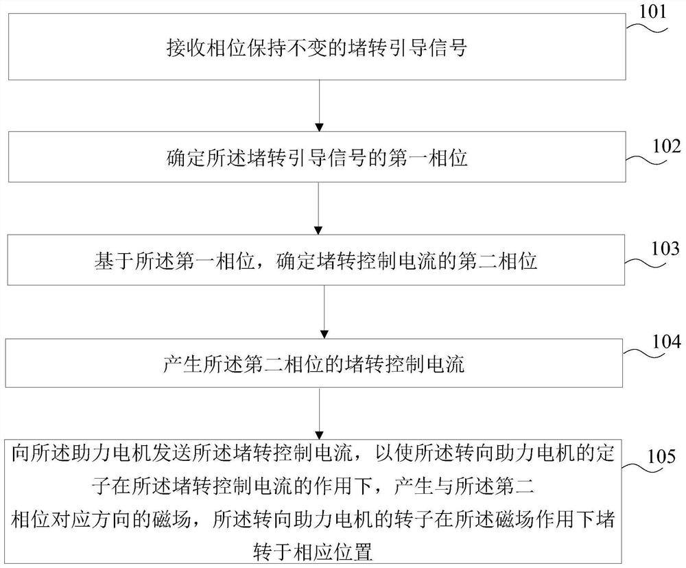
[0052] refer to figure 1 as shown, figure 1 A flow chart of a method for stalling a motor provided by Embodiment 1 of the present invention is shown. The motor stall method may comprise the steps of:

[0053] Step 101 , receiving a locked-rotor guiding signal whose phase remains unchanged.

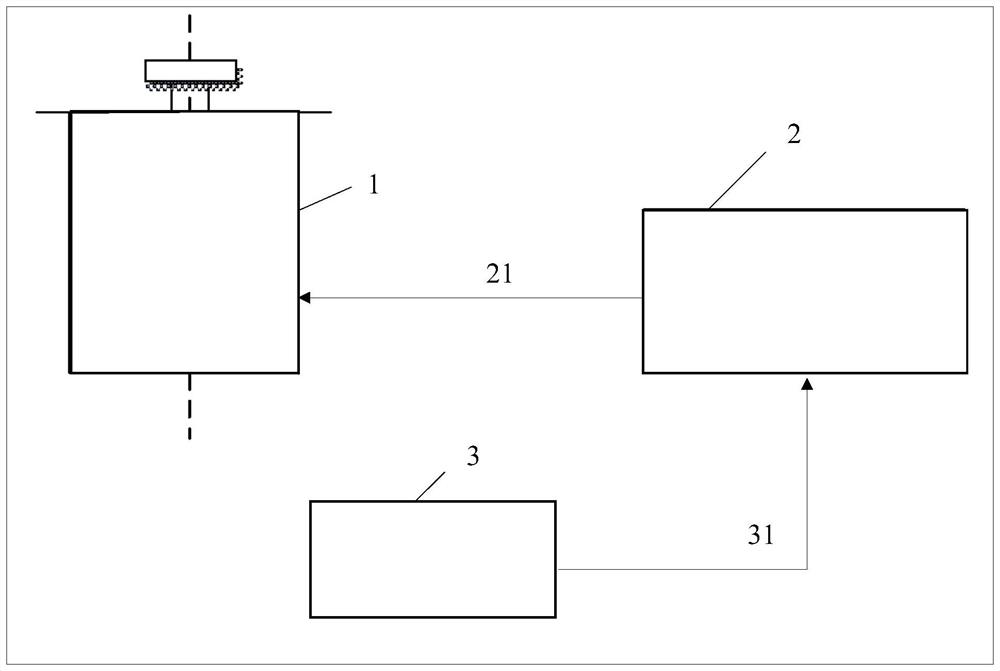
[0054] In the embodiment of the present invention, the power steering motor can be a permanent magnet synchronous motor, and the connection structure diagram of the permanent magnet synchronization and the power steering motor controller can be referred to figure 2 as shown, figure 2 A schematic diagram of the connection between the power steering motor and the motor controller is shown. When the generator 3 of the locked-rotor guiding signal is connected to the motor controller 2, it is quite necessary for the motor controller 2 to control the booster motor to generate a locked-rotor. The generating device 3 of the locked-rotor pilot signal receives the command to generate the lock...

Embodiment 2

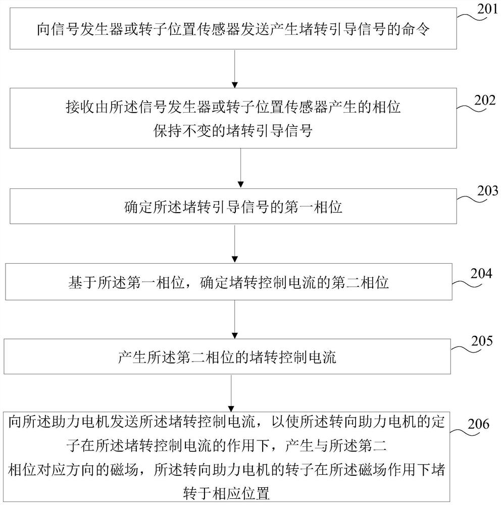
[0076] refer to image 3 as shown, image 3 A flow chart of a method for stalling a motor provided by Embodiment 2 of the present invention is shown. The motor stall method may comprise the steps of:

[0077] Step 201, sending a command to generate a locked-rotor guiding signal to a signal generator or a rotor position sensor.

[0078] In the embodiment of the present invention, a command to generate a locked-rotor guiding signal is sent to the motor controller to the signal generator or the rotor position sensor.

[0079] In a specific application, the motor controller is connected with a signal generator or a rotor position sensor, that is, it can be considered that the motor controller sends a command to generate a locked-rotor guiding signal to the signal generator or the rotor position sensor.

[0080] Optionally, when the above-mentioned generator 3 of the locked-rotor guiding signal is the above-mentioned rotor position sensor, optionally, the rotor position sensor m...

Embodiment 3

[0103] refer to Figure 5 as shown, Figure 5 It shows a motor stall device provided in Embodiment 3 of the present invention, which is applied to a power steering motor controller, and the device 300 may include:

[0104] A locked-rotor pilot signal receiving module 301, configured to receive a locked-rotor pilot signal whose phase remains unchanged;

[0105] A first phase determination module 302, configured to determine a first phase of the locked rotor pilot signal;

[0106] A second phase determination module 303, configured to determine a second phase of the locked rotor control current based on the first phase;

[0107] A locked rotor control current generating module 304, configured to generate the locked rotor control current of the second phase;

[0108] The steering assist motor control module 305 is configured to send the locked-rotor control current to the booster motor, so that the stator of the steering assist motor generates a voltage corresponding to the se...


PUM


Abstract

The present invention provides a motor stalling method and device. The method includes: receiving a stalling pilot signal whose phase remains unchanged; determining a first phase of the stalling pilot signal; and determining a stalling phase based on the first phase. the second phase of the rotation control current; generate the locked rotor control current of the second phase; send the locked rotor control current to the booster motor, so that the stator of the steering assist motor can operate at the locked rotor control current Under the action, a magnetic field in a direction corresponding to the second phase is generated, and the rotor of the power steering motor is locked in a corresponding position under the action of the magnetic field. In the motor stalling method of the present invention, the stator of the power steering motor generates a magnetic field in a corresponding direction under the action of the above-mentioned stall control current, and the rotor of the power steering motor is locked in a corresponding position under the action of the magnetic field, and the safety performance Well, it can realize the stalling at any position, which is convenient to use; no mechanical device is needed, which reduces the cost.

Description

technical field [0001] The invention relates to the technical field of electric motors, in particular to a method and device for stalling a motor. Background technique [0002] In the vehicle's electric power steering system, the power steering motor is used to provide steering power when the vehicle is turning, saving effort for the user. During the development and testing of the electric power steering system, it is necessary to conduct a stall test on the power steering motor to verify its performance and to calibrate it. [0003] At present, in the development and testing process of the electric power steering system, in order to realize the stalling of the power steering motor, the rotor of the power steering motor is usually clamped by a mechanical device, and the rotor of the power steering motor is locked. A stalled state occurs. [0004] However, the above-mentioned clamping of the rotor of the power steering motor by a mechanical device locks the rotor of the pow...

Claims


Application Information

Patent Timeline
Patent Type & Authority Patents(China)
IPC IPC(8): H02P6/24H02P6/16
CPCH02P6/16H02P6/24
Inventor 刘思远董晓王建坡部荣刘文文李浩
Owner 蜂巢智能转向系统(江苏)有限公司
Why Eureka
Try Eureka