Floating track bed

A technology for floating ballast bed and track, applied in the field of ballast bed, can solve the problems such as the inability to guarantee the most reasonable level of the vibration isolation system, the nonlinear change of the steel spring element, and the inability to achieve the best vibration isolation effect, so as to achieve a reasonable and controllable change in the natural frequency. , low vibration and noise levels, and small natural frequency variation

Active Publication Date: 2017-03-22
GERB QINGDAO VIBRATION CONTROL +1
View PDF10 Cites 8 Cited by
  • Summary
  • Abstract
  • Description
  • Claims
  • Application Information

AI Technical Summary

Problems solved by technology

However, since multiple steel spring vibration isolators are often used in this type of vibration isolation system at the same time, and each steel spring vibration isolator may contain multiple steel spring elements, under the cumulative effect of various processing errors and assembly errors , the static load provided by the self-weight of the floating plate is often unable to make all or most of the steel spring elements enter the stage of linear change in which the external force they bear is proportional to their own compression displacement, even after the rail vehicle is operated by applying a dynamic load, due to the frequency When it is higher (for example, above 10Hz), the amplitude of the vibration of the floating plate is small, and it is still possible that a considerable part of the steel spring elements are completely or partially in the working stage of nonlinear changes
In this case, the natural frequency of the entire vibration isolation system

Method used


Image

  • Floating track bed
  • Floating track bed
  • Floating track bed

Examples


Embodiment 1

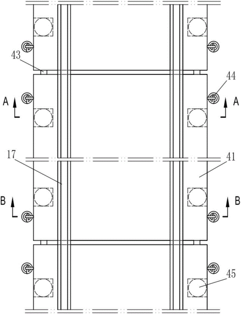
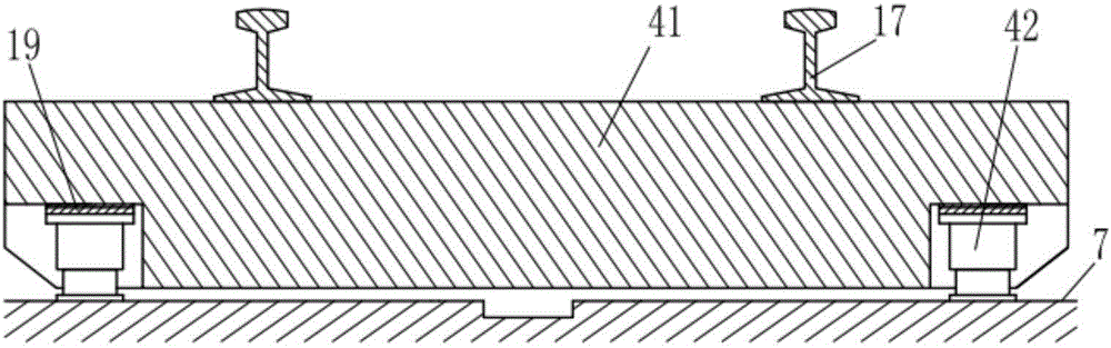
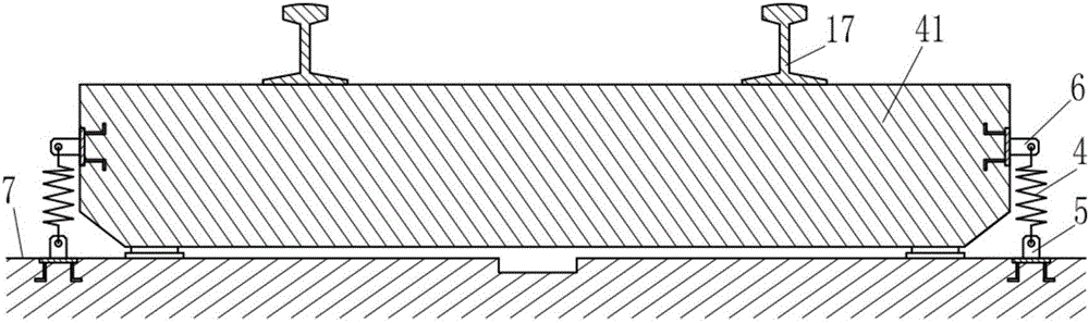
[0029] Such as figure 1 The track floating ballast bed of the present invention as shown includes a floating plate 41 and an elastic support element 45. The floating plate 41 is a side-mounted floating plate, and adjacent floating plates 41 are connected by a shear force transmission device 43. The shear force transfer device 43 is specifically a mid-mounted shear hinge, such as figure 2 and image 3 As shown, the elastic support element 45 includes a spring damping vibration isolation device 42 composed of a helical steel spring and a damping device and a height-adjusting spacer 19, wherein the damping device is specifically a viscous damping device, and the spring damping vibration isolation device 42 is located on the base 7 and the floating plate 41, the floating plate 41 is supported on the spring damping vibration isolation device 42 through the height adjustment spacer 19; in addition, it also includes a back pressure device 44, which includes a plurality of back pres...

Embodiment 2

[0034] Such as Figure 4 and Figure 5 The difference between the floating track bed of the present invention and the first embodiment is that the floating plate 41 is provided with a partial boss 31, and the boss 31 is also provided with an installation channel 12, and between adjacent floating plates 41 Connect with the shear force transfer device 43, the shear force transfer device 43 is specifically an upper-mounted shear hinge; in addition, in this example, the elastic support element is composed of a spring damping vibration isolation device 42, a height-adjusting spacer 19 and a plate end vibration isolation device 46 Composition, wherein, the spring damping vibration isolation device 42 is placed in the housing 16, the housing 16 is preset and fixed in the body of the floating plate 41, and the inside of the housing 16 is also fixedly equipped with a bearing member 18, and the middle part of the bearing member A central through hole is left, and the size of the centra...

Embodiment 3

[0037] Such as Figure 6 and Figure 7 The difference between the floating track bed of the present invention and the second embodiment is that the body of the floating plate 41 is provided with an installation channel 12; in the back pressure device 44, one end of the connecting piece 5 is fixed on the base 7 through an anchoring structure The back pressure elastic element 4 is a compression spring made of rubber spring, and the two ends of the rubber spring are also vulcanized and fixed with a pressure equalizing plate 9, and the screw of the connecting piece 5 is arranged in the installation channel 12, which runs through the floating plate 41 And the back pressure elastic element 4, utilize the locking nut 11 that screw rod top is provided with, make the back pressure elastic element 4 back pressure act on the top surface of the floating plate 41, and the force direction of the compression spring to the floating plate is consistent with the elastic support The supporting ...


PUM


Abstract

The invention belongs to a railway track bed, and discloses a floating track bed. The floating track bed comprises floating slabs and elastic supporting elements. The adjacent floating slabs are connected through shearing force transmission devices. The elastic supporting elements are located between a base and the floating slabs. The floating slabs are supported on the elastic supporting elements. The floating track bed further comprises back pressure devices which comprise back pressure elastic elements and connecting pieces. One ends of the connecting pieces are fixed to the base, and the other ends of the connecting pieces are matched with the corresponding back pressure elastic elements. The floating track bed disclosed by the invention is simple in structure, system inherent frequency variation is reasonable and controllable, the vibration and noise levels are low, the vibration adsorbing and noise reducing performance is stable, the vibration isolating efficiency is high, the service life is long, the safety is better, and the floating track bed can be widely applied to track bed structures of different rail transit types including railways, metros, urban railways, elevated railways, high speed railways and the like and has wide market application prospects.

Description

technical field [0001] The invention belongs to a railway track bed, and in particular relates to a track structure of a railway, which may specifically be a track bed of a railway, a subway, an urban railway, an elevated light rail, a high-speed railway, or the like. Background technique [0002] Vibration and noise are recognized as the most widely affected public hazards, and they are also a problem that needs to be solved urgently in the development of rail transit in recent years. Among the existing rail transit vibration and noise reduction technologies, the most successful practical application is the component floating technology, typically the floating ballast bed technology, which has high vibration isolation efficiency and stable working performance, which has become a consensus in the industry. In particular, the floating ballast bed with the new prefabricated short floating slab structure has been widely recognized by the market and users due to its advantages o...

Claims


Application Information

Patent Timeline
IPC IPC(8): E01B1/00E01B19/00
CPCE01B1/002E01B19/003E01B2204/06E01B2204/09E01B2204/12
Inventor 尹学军谭文邹东王进刘浪静黄红东姚力刘焕欣党红玲刘铁民王建立孔祥斐王建
Owner GERB QINGDAO VIBRATION CONTROL
Why Eureka
Try Eureka