Bullet charging and discharging device and quick bullet charging and discharging method thereof

A bomb unloader, fast technology, applied in the direction of grappling hooks, weapon accessories, ammunition supply, etc., can solve the complex processing, assembly and adjustment of the loading and unloading device, and cannot solve the problem of fast loading and unloading of the magazine, Can not be used in all-weather environment and other problems, to achieve the effect of compact and compact overall shape, stable and reliable working state, and convenient unloading

Active Publication Date: 2017-10-03
贺佳琪 +1
View PDF8 Cites 4 Cited by
  • Summary
  • Abstract
  • Description
  • Claims
  • Application Information

AI Technical Summary

Problems solved by technology

Therefore, it is inconvenient to load the ammunition, especially the problem of fast reloading of the magazine cannot be solved, and it cannot be used in an all-weather environment.
And there is no unloading technology and any tool in the prior art
[0003] In short, at present, it is inconvenient to load and unload ammunition, the manual operation is intensive, and it lacks a stable and reliable working state. In particular, it cannot solve the problem of fast loading and unloading of the magazine. cannot adapt to the use of
The processing, assembly and adjustment of the loading and unloading device are complicated, and the manufacturing cost is relatively high
[0004] In order to overcome the shortcomings of clothing and slow unloading speed, making loading and unloading fast and convenient is an important technical issue currently facing

Method used


Image

  • Bullet charging and discharging device and quick bullet charging and discharging method thereof
  • Bullet charging and discharging device and quick bullet charging and discharging method thereof
  • Bullet charging and discharging device and quick bullet charging and discharging method thereof

Examples


Embodiment Construction

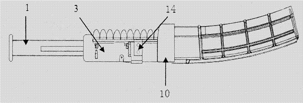
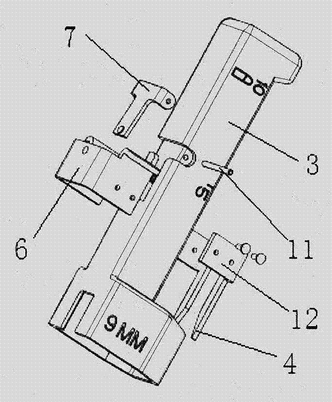
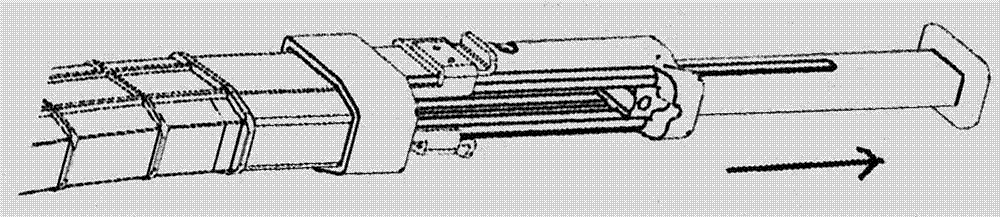
[0025] refer to figure 1 , The loading and unloading device of the present invention includes a bomb holding slot 3, a push bar 1 and a bomb unloading device 14. Among them, refer to Image 6 , The bomb holding slot 3 is provided with a front bag mouth 10 that is movably connected with the magazine. The bullet-holding groove 3 is a rectangular groove, and the two inner walls of the bullet-holding groove 3 are respectively provided with sliding grooves 17 . combined reference Figure 2 to Figure 4 , The push rod 1 is a bar-shaped cube, and its two outer walls are respectively provided with boss keys 9 matched with the sliding groove 17. The rear end of the bomb holding groove 3 is provided with a rear bag opening 19, and the rear bag opening 19 is provided with a limit groove 18, and the front end of the push bar 1 is provided with a limit catch 2, and the limit stop tenon 2 is movably matched with the limit groove 18. Limiting tenon 2 is installed in the limit groove by th...


PUM


Abstract

The invention provides a bullet charging and discharging device which comprises a bullet containing groove, a bullet push rod and a bullet discharging device. The bullet containing groove is provided with a front bag opening movably connected with a box magazine. Sliding grooves are formed in the two inner side walls of the bullet containing groove, the bullet push rod is a strip-shaped cube, and boss keys matched with the sliding grooves are arranged on the two outer side walls of the bullet containing groove. A back bag opening is formed in the back end of the bullet containing groove, a limiting groove is formed in the back bag opening, and a limiting clamping tenon is arranged at the front end of the bullet push rod and is movably matched with the limiting groove. The bullet discharging device comprises a T-shaped positioning bullet sheet, an L-shaped insertion needle and a U-shaped sliding plate. The invention further provides a quick bullet charging and discharging method for the bullet charging and discharging device. The bullet charging and discharging device has the beneficial effects that bullet charging and discharging are convenient, machining, assembling and adjusting are facilitated, the working state is stable and reliable, the manufacturing cost is low, carrying is easy, the bullet charging and discharging device is suitable for being used in all-weather environments, quick bullet charging is achieved, the failure rate is approximately zero, the bullet discharging device can be easily and stably used, and quick bullet discharging is achieved.

Description

technical field [0001] The invention relates to a tool, in particular to a loading and unloading device and a method for quickly loading and unloading the bomb. Background technique [0002] At present, in the process of feeding bullets to the magazine, bullets are pressed into the magazine one by one by manual, manual, and single shots to realize the feeding. Therefore, it is inconvenient to load the ammunition, especially the problem of fast reloading of the magazine cannot be solved, and it cannot be used in an all-weather environment. And there is no unloading technology and any tool in the prior art. [0003] In short, at present, loading and unloading ammunition is inconvenient, manual operation is intensive, and there is no stable and reliable working state, especially the problem of fast loading and unloading of magazines cannot be solved. Therefore, for the all-weather environment of gun loading and unloading cannot be adapted to use. The processing, assembly and...

Claims


Application Information

Patent Timeline
Patent Type & Authority Applications(China)
IPC IPC(8): F41A9/39F41A15/22
CPCF41A9/39F41A15/22
Inventor 贺佳琪贺龙飞
Owner 贺佳琪
Why Eureka
Try Eureka