
Automatic insertion and positioning device for injection-molded embedded hardware

A positioning device and hardware technology, applied in the direction of coating, etc., can solve the problems of easy reverse insertion, heavy workload, high labor cost, etc., and achieve the effect of avoiding reverse installation and improving work efficiency

Pending Publication Date: 2019-12-13
江苏骏伟精密部件科技股份有限公司
View PDF0 Cites 3 Cited by
  • Summary
  • Abstract
  • Description
  • Claims
  • Application Information

AI Technical Summary

Problems solved by technology

In the prior art, the hardware parts are usually inserted into the fixtures manually first, which requires a lot of work, high labor costs, and the problem of easy reverse insertion, which needs to be improved.

Method used


Image

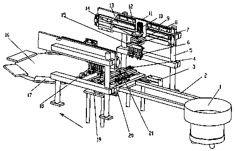
  • Automatic insertion and positioning device for injection-molded embedded hardware
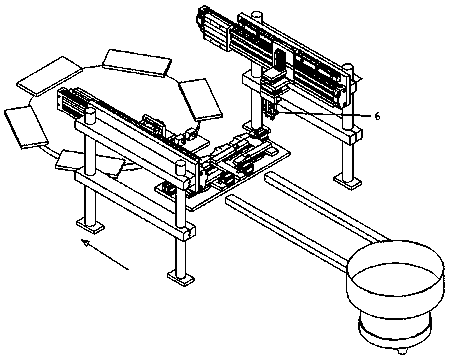
  • Automatic insertion and positioning device for injection-molded embedded hardware

Examples


Embodiment Construction

[0019] The following will clearly and completely describe the technical solutions in the embodiments of the present invention. Obviously, the described embodiments are only some of the embodiments of the present invention, rather than all the embodiments. Based on the embodiments of the present invention, all other embodiments obtained by persons of ordinary skill in the art without making creative efforts belong to the protection scope of the present invention.

[0020] see Figure 1~Figure 2 , the embodiment of the present invention includes:

[0021] Such as figure 1 and figure 2 The shown automatic plug-in positioning device for injection molded embedded hardware includes: vibrating plate 1, material guide trough body 2, workbench 19, hardware fixing device, turntable 16, clamp 18 and hardware grabbing and transferring mechanism. The vibrating plate 1 is arranged in front of the workbench 19, and hardware is arranged in the vibrating plate 1 to arrange and output the h...


PUM


Abstract

The invention discloses an automatic insertion and positioning device for injection-molded embedded hardware. The automatic insertion and positioning device comprises a vibrating disk, a guide chute body, a workbench, hardware fixing devices, a rotary table, clamps and hardware grabbing and transferring mechanisms, wherein a mobile carrier is arranged on the workbench, and the hardware fixing devices are arranged on the mobile carrier at intervals; the guide chute body is arranged at a discharging port of the vibrating disk and points to the mobile carrier; the hardware grabbing and transferring mechanisms are arranged on one side or two sides of the mobile carrier and the guide chute body and transfer hardware on the guide chute body onto the hardware fixing devices; a plurality of clampfixing seats are arranged on the rotary table in a mode of a ring array; and the clamps are respectively arranged on the clamp fixing seats. By the way, the automatic insertion and positioning devicefor the injection-molded embedded hardware avoids the problem that the hardware is installed backwards, and improves the working efficiency of the hardware being inserted into the clamps.

Description

technical field [0001] The invention relates to the technical field of injection molded parts production, in particular to an automatic insertion positioning device for injection molded pre-embedded hardware. Background technique [0002] With the continuous development of the industry, the functional requirements of injection molding products are getting higher and higher, especially the injection molding parts containing hardware circuits. Since the hardware circuits need to conduct electricity and cannot be short-circuited, the positioning accuracy is high, and positioning in the mold is required. [0003] In order to improve the relative accuracy of the hardware circuit, a plurality of hardware components constituting the hardware circuit can be positioned through the fixture first, and then put into the mold together with the fixture. In the prior art, the hardware is usually manually inserted into the fixture respectively, which requires heavy workload, high labor cost...

Claims


Application Information

Patent Timeline
Patent Type & Authority Applications(China)
IPC IPC(8): B29C45/14
CPCB29C45/14B29C2045/1486
Inventor 汤秋梅张夕松
Owner 江苏骏伟精密部件科技股份有限公司
Learn More