
Recoil arc extinguishing insulator

A technology of insulators and insulator strings, which is applied in the field of lightning protection for power transmission and distribution overhead lines, can solve problems such as reducing the parallel gap and insulator insulation coordination ability, reducing line insulation level, and installation difficulty, so as to improve the range of overvoltage suppression and self- Durability, elimination of power frequency large arc, and the effect of safety advantages

Inactive Publication Date: 2019-12-13
南宁超伏电气科技有限公司
View PDF0 Cites 0 Cited by
  • Summary
  • Abstract
  • Description
  • Claims
  • Application Information

AI Technical Summary

Problems solved by technology

[0003] Nowadays, the lightning arresters and parallel gaps widely used in power lines mainly intervene when lightning strikes occur. Traditional lightning arresters have many disadvantages, such as: difficult maintenance, low lightning protection effect, and inability to protect against superimposed lightning strikes, etc.
There are also many disadvantages in the parallel gap, for example: (1) The installation of the parallel gap requires additional fittings, which is difficult to install; (2) The insulation coordination of the parallel gap is designed according to the highest breakdown voltage of the two insulators at the head and tail of the insulator string. At the beginning and end, the insulation mix ratio that leads to the parallel gap needs to be very low, which will reduce the insulation level of the line and lead to an increase in the lightning trip rate; Causes the metal electrode to be ablated, reducing the insulation coordination ability between the parallel gap and the insulator

Method used


Image

  • Recoil arc extinguishing insulator
  • Recoil arc extinguishing insulator
  • Recoil arc extinguishing insulator

Examples


Embodiment Construction

[0033] In order to make the object, technical solution and advantages of the present invention clearer, the present invention will be described in further detail below with reference to the accompanying drawings and preferred embodiments. However, it should be noted that many of the details listed in the specification are only for readers to have a thorough understanding of one or more aspects of the present invention, and these aspects of the present invention can be implemented even without these specific details.

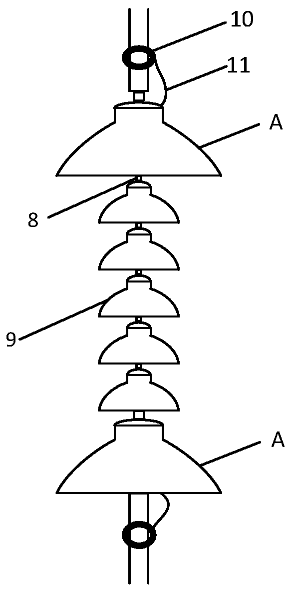
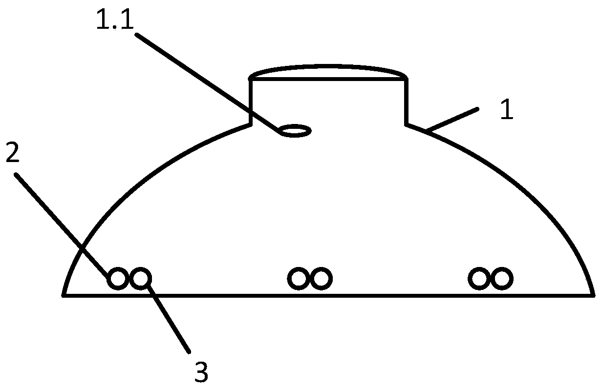
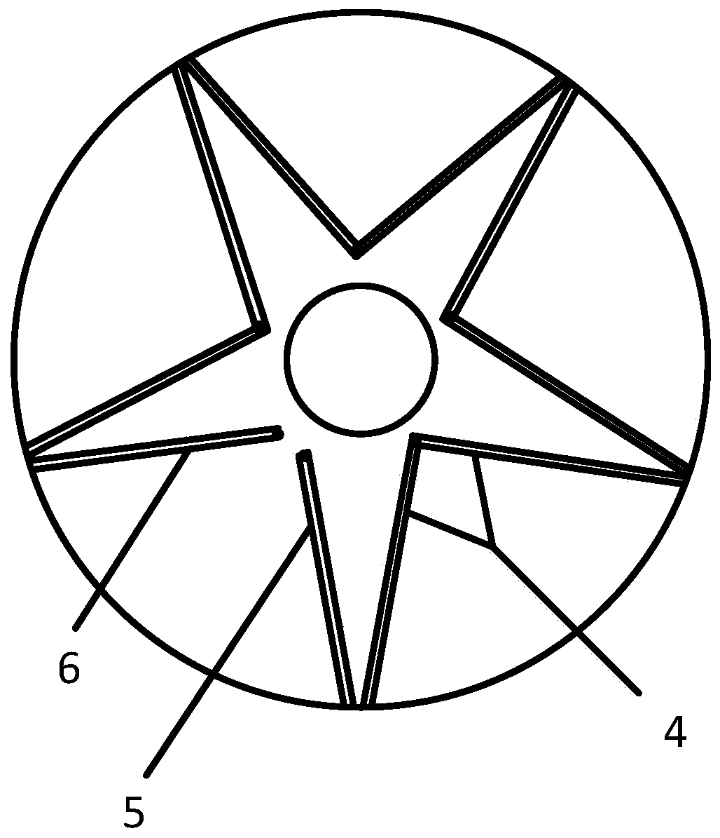
[0034] According to the above principle description and reference figure 1 The embodiment of the present invention is further described:

[0035]A recoil arc extinguishing insulator, comprising several insulators 9 and connecting rods 8, several insulators 9 are connected in series through the connecting rods 8 to form an insulator string, and it is characterized in that recoil arc extinguishing devices are arranged at both ends of the insulator string, The arc ...


PUM


Abstract

The invention discloses a recoil arc extinguishing insulator, and belongs to the technical field of lightning protection of power transmission and distribution overhead lines. The recoil arc extinguishing insulator comprises a plurality of insulators and a connecting rod, wherein the plurality of insulators are connected in series through the connecting rod to form an insulator string, and is characterized in that two ends of the insulator string are respectively provided with recoil arc extinguishing devices, each recoil arc extinguishing device comprises an arc guiding electrode, a wire andan end insulator, and the arc guiding electrode is arranged on an external connecting piece and is connected to the end insulator through the wire. According to the invention, the arc extinguishing time of the insulator is advanced, the traditional through flashover insulation matching is advanced to the local flashover insulation matching, most of the insulation is not broken down after local flashover, only creeping discharge occurs, and an arc extinguishing object is only the current of an extremely weak impact arc at the moment, so that the insulator is high in vulnerability and low in arcextinguishing difficulty.

Description

technical field [0001] The invention relates to the technical field of lightning protection for power transmission and distribution overhead lines, in particular to a recoil arc-extinguishing insulator. Background technique [0002] When the thundercloud gathers to form the potential difference between the thundercloud and the earth, a very uneven electric field is always induced at the insulator. Research shows that the distribution of electric field intensity between different numbers of insulators is also very uneven when lightning strikes occur, which is manifested as high electric field intensity at both ends of the insulator string and low electric field intensity at the middle part. Due to the high electric field intensity of the insulators at the first and last ends, and the low electric field intensity in the middle of the insulator, lightning flashover arcs first appear at both ends of the insulator string, and then develop from both ends of the insulator string to...

Claims


Application Information

Patent Timeline
IPC IPC(8): H01B17/04H01B17/48H01B17/46H01T1/02H01T19/00
CPCH01B17/04H01B17/46H01B17/48H01T1/02H01T19/00
Inventor 王锟张清河徐宇恒彭斐黄萍李继强王国锋骆耀敬王巨丰王嬿蕾
Owner 南宁超伏电气科技有限公司
Learn More