
UAV layout with least control surface configurations and control method for same

A control method and unmanned aerial vehicle technology, applied in the direction of control start-up method, human manipulation, etc., to achieve the effect of aerodynamic resistance, strong applicability, and enhanced robustness

Active Publication Date: 2019-12-17
NORTHWESTERN POLYTECHNICAL UNIV
View PDF7 Cites 4 Cited by
  • Summary
  • Abstract
  • Description
  • Claims
  • Application Information

AI Technical Summary

Problems solved by technology

[0007] In order to avoid the deficiencies of the prior art, the present invention proposes a UAV layout with the least rudder surface configuration and its control method, which mainly solves the following problems existing in the existing UAV layout and control methods:

Method used


Image

  • UAV layout with least control surface configurations and control method for same
  • UAV layout with least control surface configurations and control method for same
  • UAV layout with least control surface configurations and control method for same

Examples


Embodiment Construction

[0051] The embodiments described below by referring to the figures are exemplary and are intended to explain the present invention and should not be construed as limiting the present invention.

[0052] In describing the present invention, it should be understood that the terms "center", "longitudinal", "transverse", "length", "width", "thickness", "upper", "lower", "front", " Orientation indicated by rear, left, right, vertical, horizontal, top, bottom, inside, outside, clockwise, counterclockwise, etc. The positional relationship is based on the orientation or positional relationship shown in the drawings, which is only for the convenience of describing the present invention and simplifying the description, rather than indicating or implying that the referred device or element must have a specific orientation, be constructed and operated in a specific orientation, Therefore, it should not be construed as limiting the invention.

[0053] The following is a typical applicatio...


PUM


Abstract

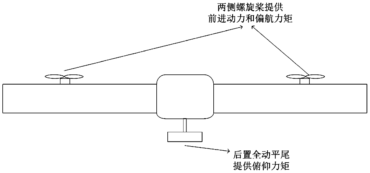
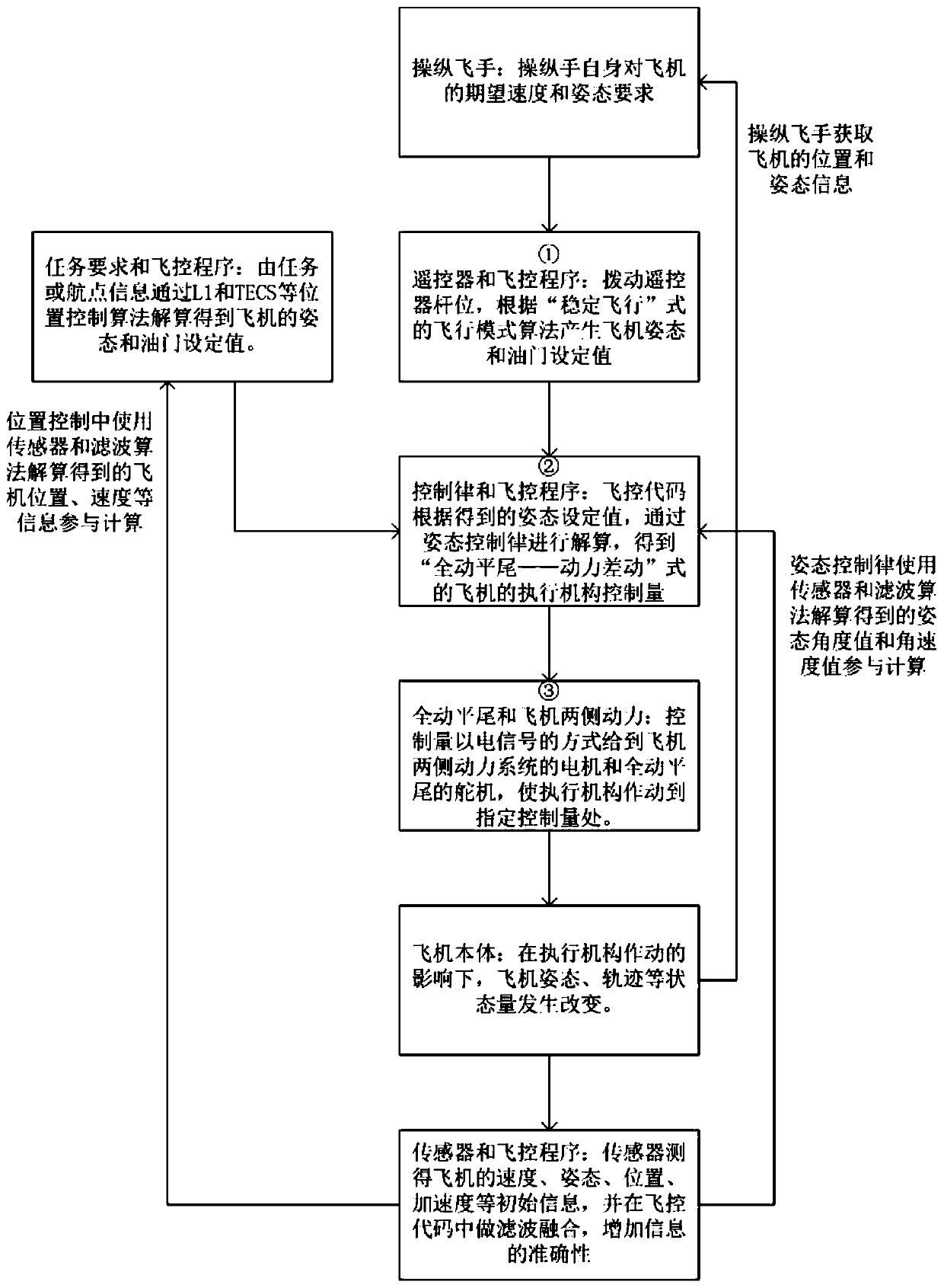
The invention provides a UAV layout with the least control configurations and belongs to the technical field of flight vehicle design and flight control. A UAV comprises a plane body, wings on both sides, engines on both sides and a stabilator, wherein the engines on the both sides are fixed under the wings on the both sides respectively, and the stabilator is fixed on the tail part of the plane body; and horizontal course control of the UAV is realized by the engines on the both sides of the plane body, and longitudinal control of the UAV is realized by deflection of the stabilator. The UAV layout provided by the invention has the beneficial effects that only one stabilator is disposed on a control pneumatic control surface of the UAV, so a resistance generation face is greatly reduced during UAV design and flight resistance is reduced without addition of an extra control execution mechanism; the least control surface is used for control, and the quantity of the control execution mechanism is minimized, so energy consumption generated from control can be reduced to a certain extent; and overall deflection of the stabilator is used, so steerage effects of control are increased as much as possible on the premise that a horizontal tail area is reduced and thus UAV control is more sensitive and effective.

Description

technical field [0001] The invention belongs to the technical field of aircraft design and flight control, and in particular relates to an unmanned aerial vehicle layout with minimum rudder surface configuration and a control method thereof. Background technique [0002] Most of the existing traditional fixed-wing UAVs use a combination of ailerons, elevators and rudders for flight manipulation and control of UAVs. In this method, rudder surfaces that rotate around the axis are respectively installed on the wings, vertical tail and flat tail of the drone to form ailerons, rudders, and elevators. When the aircraft is flying, the three rudder surfaces rotate around the axis to change the position of the wings and tail. The air pressure distribution generates the aerodynamic moment that makes the drone rotate around three different fuselage axes, realizes the change of the drone's attitude, and then controls the attitude and trajectory of the drone. [0003] However, this kind...

Claims


Application Information

Patent Timeline
Patent Type & Authority Applications(China)
IPC IPC(8): B64C13/04B64C13/08
CPCB64C13/04B64C13/08
Inventor 周洲陈明哲王睿
Owner NORTHWESTERN POLYTECHNICAL UNIV
Learn More