
System and method for monitoring leakage of non-metal pipeline

A pipeline leakage, non-metallic technology, applied in the pipeline system, by detecting the appearance of fluid at the leakage point, using liquid/vacuum degree for liquid tightness measurement, etc., can solve the problem of fast sound wave attenuation, large noise interference, and lack of leakage Monitoring technology and other issues, to achieve the effect of easy implementation, simple detection equipment, and cost reduction

Pending Publication Date: 2019-12-17
诸暨市逍遥管道科技有限公司
View PDF0 Cites 7 Cited by
  • Summary
  • Abstract
  • Description
  • Claims
  • Application Information

AI Technical Summary

Problems solved by technology

This method has been successfully applied in metal pipelines, but in non-metal pipelines, due to the fast attenuation speed of sound waves in non-metal (plastic) materials, the propagation distance is short, and the system construction cost is high.
Moreover, this method is greatly disturbed by external noise and produces many false alarms, so the acoustic wave detection technology cannot be applied to the leakage of non-metallic pipelines
In optical fiber detection technology, it is difficult to decouple the optical fiber signal due to the influence of temperature and strain factors, and the optical fiber material is easy to break, requiring special maintenance, which limits its application
Therefore, in the leakage monitoring of non-metallic pipelines, there is still a lack of an effective leakage monitoring technology.

Method used

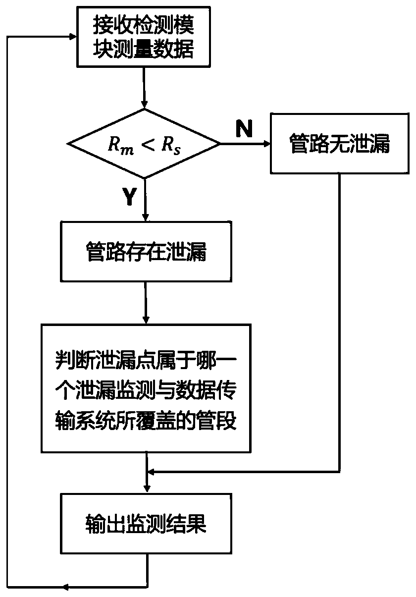

Image

  • System and method for monitoring leakage of non-metal pipeline
  • System and method for monitoring leakage of non-metal pipeline
  • System and method for monitoring leakage of non-metal pipeline

Examples


Embodiment example

[0056] This implementation case implements monitoring according to the following steps:

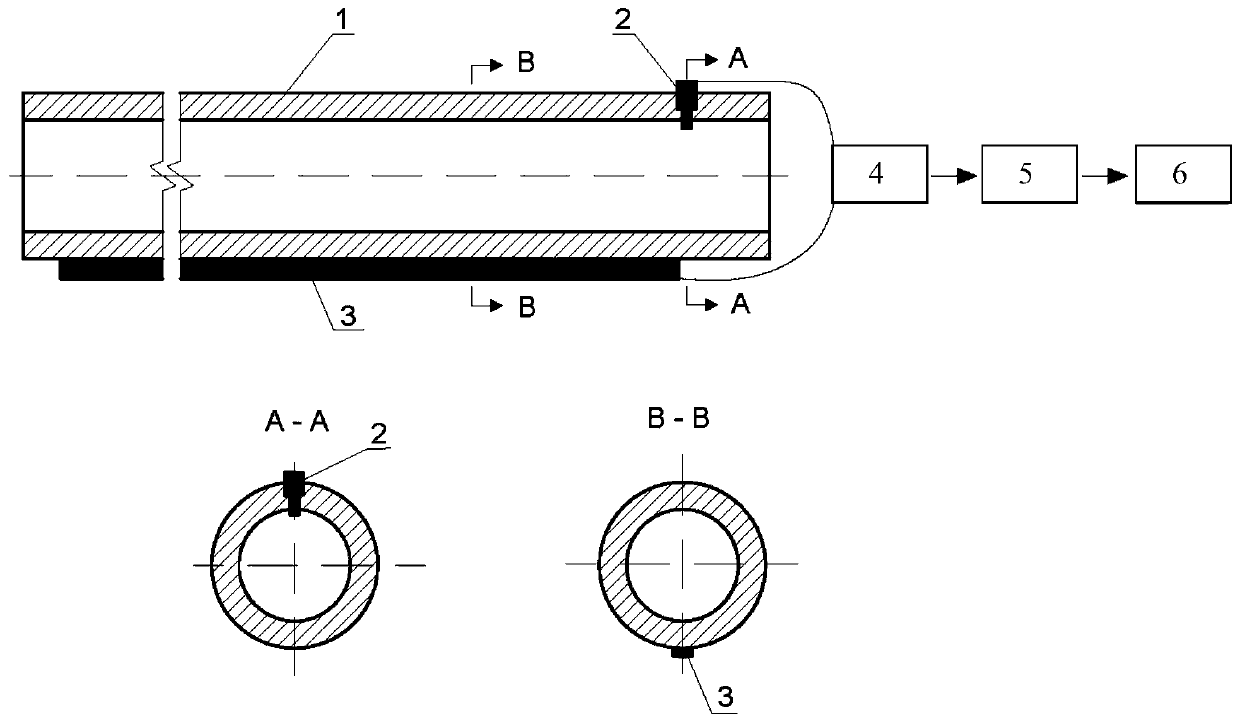
[0057] (1) According to figure 1 The monitoring electrodes and multimeters are arranged as shown, and the filling medium in the pipeline is water;

[0058] (2) When there is no leakage in the pipeline, use a multimeter (maximum measurement resistance 200MΩ) to measure the resistance value between the axial monitoring electrode 3 and the circumferential monitoring electrode 2. The measurement result shows that the resistance value exceeds the range, which is recorded as R 0 ;

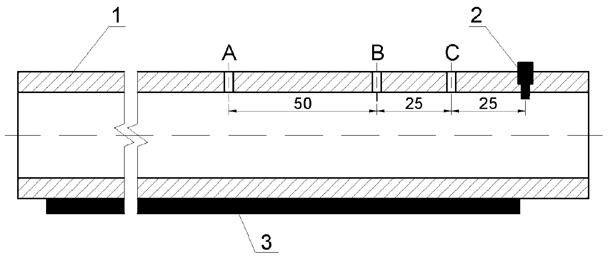
[0059] (3) if image 3 As shown, a hole A is drilled on the pipeline at a distance of 100cm from the circumferential monitoring electrode (the axial distance between point A and the circumferential monitoring electrode) to simulate pipeline leakage. At the lowermost axial monitoring electrode 3, the leaked water and the water in the pipeline will connect the axial monitoring electrode 3 and the circumferential mo...


PUM


Abstract

The invention relates to a pipeline leakage monitoring technology, and aims to provide a system and a method for monitoring leakage of a non-metal pipeline. The system comprises a resistance value detection module, an axial monitoring electrode which is arranged right below the outer side of the pipeline in the axial direction, and an annular monitoring electrode which is arranged on the wall of the pipeline and can be in contact with a conveyed medium, one end of the axial monitoring electrode is sequentially connected with the resistance value detection module and the annular monitoring electrode through wires, the annular monitoring electrode and the terminal of the annular monitoring electrode are kept insulated from the axial monitoring electrode and the pipeline installation environment, the resistance value detection module is connected with a communication module through a signal line, the communication module is connected to a leakage analysis module in a wired or wireless communication mode, and the leakage analysis module is used for judging whether pipeline leakage occurs or not according to the resistance monitoring data change uploaded by the communication module. Detection equipment adopted by the system and the method is simple, complex detection equipment is not needed, the test method is easy to realize, and the cost of non-metal pipeline leakage monitoring isreduced.

Description

technical field [0001] The invention relates to pipeline leakage monitoring technology, in particular to a system and method for monitoring non-metallic pipeline leakage. Background technique [0002] Pipelines are the core facilities for energy and water transportation, and are the lifelines for national economic development and human survival. With the adjustment of my country's energy structure and the acceleration of urbanization, non-metallic pipelines are widely used in major national projects, such as high-pressure jumper pipes in tidal flats and shallow sea oil industry, and gas transmission pipelines in urban gas pipeline networks. , as a cooling water circulation pipe in nuclear power plants, and it is also an ideal substitute for oil well water injection pipes and shallow sea medium and low pressure marine hoses. my country has become the country with the largest output and demand of non-metallic pipes, and the application prospects are very broad. [0003] Non-m...

Claims


Application Information

Patent Timeline
Patent Type & Authority Applications(China)
IPC IPC(8): F17D5/06G01M3/18G01R27/02
CPCF17D5/06G01M3/18G01R27/02
Inventor 施昌高胡征宇卓章明
Owner 诸暨市逍遥管道科技有限公司
Learn More