Ploughing machine
A technology of tiller and frame, applied in the field of tiller, can solve the problems of inconvenient walking, damage, easy deviation of walking direction, etc., and achieve good tillage effect.
- Summary
- Abstract
- Description
- Claims
- Application Information
AI Technical Summary
Problems solved by technology
Method used
Image

Examples
Embodiment Construction
[0017] In order to make the purpose, structure and advantages of the present invention clearer, the embodiments of the present invention will be further described in detail below in conjunction with the accompanying drawings.
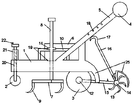
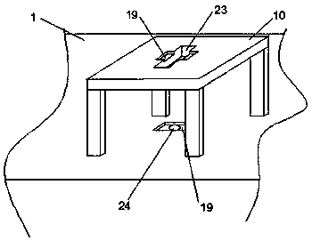
[0018] Such as Figure 1-Figure 2 As shown, the present invention is realized by taking the following technical solutions: a tiller comprising a frame 1, an armrest frame 4, a supporting wheel 2 and a traveling wheel 3. The support wheel is located at the front, and its diameter is smaller than the walking wheel. It is used as a walking front wheel when it is not working, and it is mainly used as an adjustment device for plowing depth limit when it is working. The support wheel is connected with the cylinder 21 fixed on the frame top by the screw rod 11, the cylinder is provided with internal thread, the screw rod is penetrated in the cylinder, and the top of the screw rod is provided with a rotating handle 22. Walking wheel has two, links to each othe...
PUM
 Abstract
Description
Claims
Application Information
 - R&D
- Intellectual Property
- Life Sciences
- Materials
- Tech Scout
- Unparalleled Data Quality
- Higher Quality Content
- 60% Fewer Hallucinations
Browse by: Latest US Patents, China's latest patents, Technical Efficacy Thesaurus, Application Domain, Technology Topic, Popular Technical Reports.
© 2025 PatSnap. All rights reserved.Legal|Privacy policy|Modern Slavery Act Transparency Statement|Sitemap|About US| Contact US: help@patsnap.com