
Pot handle

A technology of handles and movable rakes, which can be used in home appliances, applications, kitchen utensils, etc. It can solve the problems of unfavorable washing, waste of food, inconvenient use, etc., and achieve the effect of fast connection and detachment, low production cost, and firm locking

Inactive Publication Date: 2019-12-20
FEM IND
View PDF0 Cites 0 Cited by
  • Summary
  • Abstract
  • Description
  • Claims
  • Application Information

AI Technical Summary

Problems solved by technology

[0003] Pots with handles are usually fixed together with the handle and the pot body, and the two form a non-detachable type, but permanently fixing the handle together will cause the pot to take up a lot of space, which is not conducive to washing (such as placing it in a dishwasher) middle cleaning), it is also not conducive to collection
For pots without handles, such as the liner in the electric rice cooker, various soup pots, frying pans, and pressure cooker liners, etc., people usually need to use liners to avoid burning their hands when lifting such pots. This brings inconvenience to use, and the pot cannot be lifted at any time
If the pot is tipped over during the lifting process, it will not only waste food, but also cause safety hazards such as burns

Method used


Image

  • Pot handle
  • Pot handle
  • Pot handle

Examples


Embodiment 1

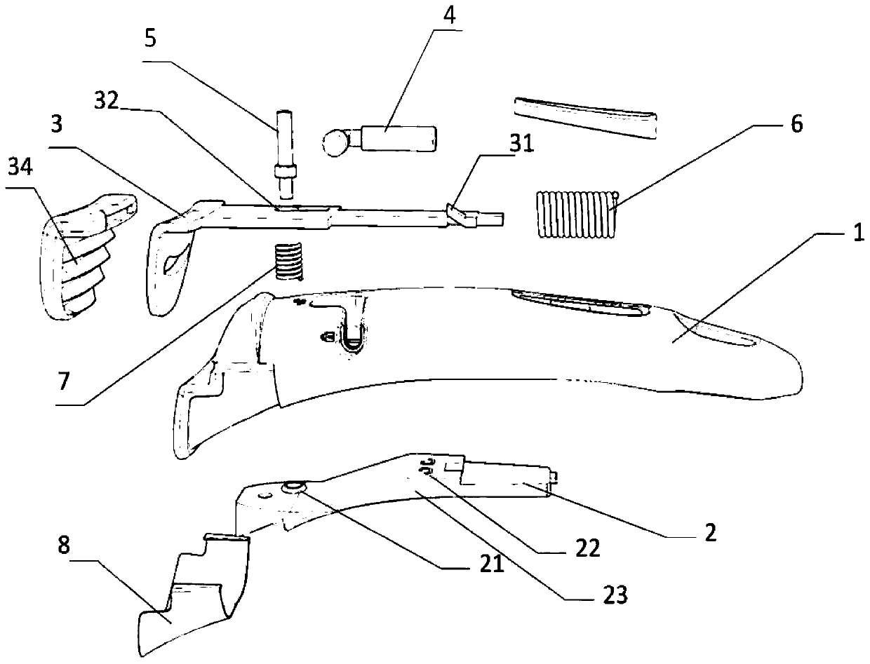
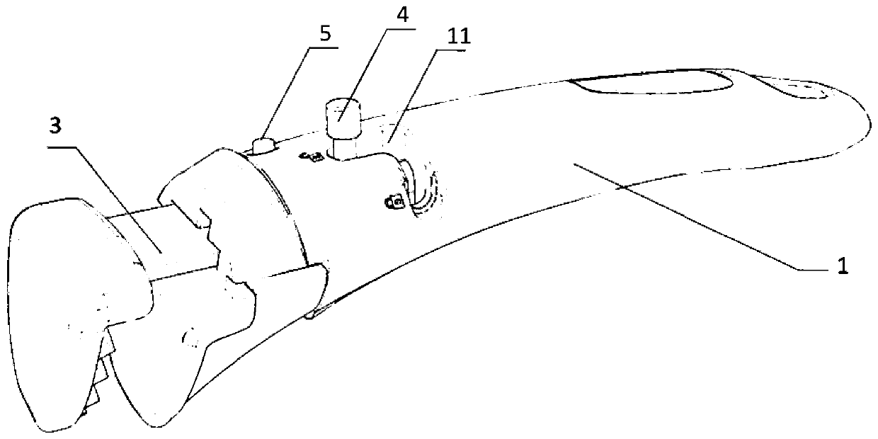
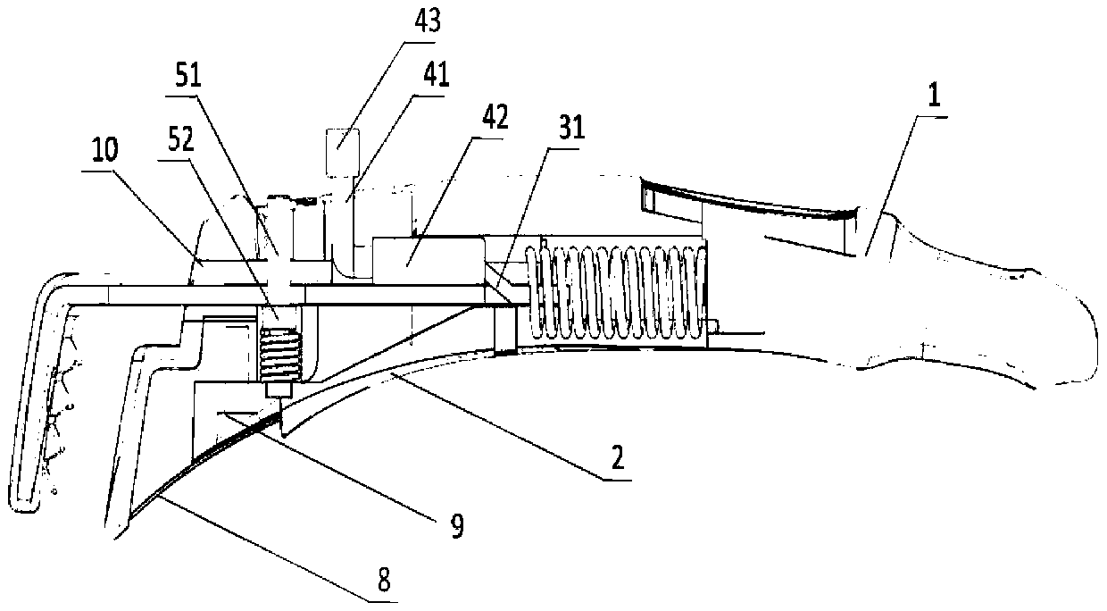
[0026] A pot handle such as figure 1 Shown, there is main body 1 on the handle, main body 2 under the handle, movable rake 3, driving lever 4, safety bolt 5, the first elastic member 6, the second elastic member 7.

[0027] The movable rake 3, preferably a steel rake, especially a stainless steel rake, is located in the channel groove 10 in the main body on the handle, as Figure 2B shown. When in an active state, the movable rake 3 can move within the channel slot 10 .

[0028] Such as Figure 5A As shown, the front end of the movable rake 3 is a rake head 30, which is used to clamp the pot wall between the movable rake and the upper body of the handle. The rake head 30 at the front end of the movable rake is used to contact the position of the pot wall, preferably has a shape suitable for clamping the pot body, such as a curved surface (such as Figure 5A Shown) to fit the pot wall; it is also preferably provided with a protective cover 34, which can cover a heat-resista...

Embodiment 2

[0055] The difference between embodiment 2 and embodiment 1 is that further preferably, the lower body 2 of the handle is provided with a drain groove 22 , such as a C-shaped through hole of the drain groove, for draining accumulated water in the handle.

[0056] Draining stagnant water can prolong the service life of stainless steel materials, prevent mold growth, and ensure the sanitation of the food cooking process. The design of the drain makes this handle more suitable for cleaning and washing in the dishwasher.

Embodiment 3

[0058] The difference between embodiment 3 and embodiment 2 is: a cover plate 8 is equipped with on the front portion of the lower main body 2 of the handle, such as steel plate, preferably stainless steel. The cover plate 8 covers the installation hole 9 for connecting the handle upper body 2 and the handle lower body 2 .

[0059] After assembly, the middle part of the main body 2 under the handle forms a step with the cover plate 8 to prevent the hands from moving to the stainless steel cover plate 8 and prevent hot hands.

[0060] In addition, the lower side of the cover plate 8 has a broad side 23, which is also beneficial to prevent hot hands.


PUM


Abstract

The invention discloses a pot handle which comprises a handle upper body, a handle lower body, a movable harrow, a first elastic member, a first locking mechanism and a second locking mechanism. The pot handle can be used for directly lifting a pot body without a handle; and through a double-safety locking structure, a lock structure is more stable, heavier pots and foods in the pots can be lifted, meanwhile, misoperation is avoided, and safety and reliability are better achieved.

Description

technical field [0001] The invention relates to the field of cooking utensils, in particular to a pot handle, in particular to a handle that can be easily detached from the pot. Background technique [0002] Pot is a kitchen utensil commonly used in people's daily life. There are roughly two types of pots in the prior art, one is a pot with a handle, and the other is a pot without a handle. [0003] Pots with handles are usually fixed together with the handle and the pot body, and the two form a non-detachable type, but permanently fixing the handle together will cause the pot to take up a lot of space, which is not conducive to washing (such as placing it in a dishwasher) middle cleaning), which is also not conducive to collection. For pots without handles, such as the liner in the electric rice cooker, various soup pots, frying pans, and pressure cooker liners, etc., people usually need to use liners to avoid burning their hands when lifting such pots. This makes it inc...

Claims


Application Information

Patent Timeline
Patent Type & Authority Applications(China)
IPC IPC(8): A47J45/07
CPCA47J45/071
Inventor 林日夑金明河
Owner FEM IND
Learn More