Control method of electric vehicle charging cover and charging socket

A technology of a charging socket and a control method, which is applied in the direction of electric vehicle charging technology, electric vehicles, charging stations, etc., can solve problems such as cumbersome operation, and achieve the effects of optimizing logic, reducing interference, and facilitating identification and processing

Pending Publication Date: 2019-12-20
JIANGMEN TIANDE ELECTRICAL APPLIANCE CO LTD
View PDF1 Cites 4 Cited by
  • Summary
  • Abstract
  • Description
  • Claims
  • Application Information

AI Technical Summary

Problems solved by technology

[0004] The purpose of the present invention is to provide a method for controlling the charging cover of an electric vehicle, which can improve the problem of tedious traditional charging operations, and provide a corresponding electric vehicle charging socket

Method used


Image

  • Control method of electric vehicle charging cover and charging socket
  • Control method of electric vehicle charging cover and charging socket
  • Control method of electric vehicle charging cover and charging socket

Examples


Embodiment 1

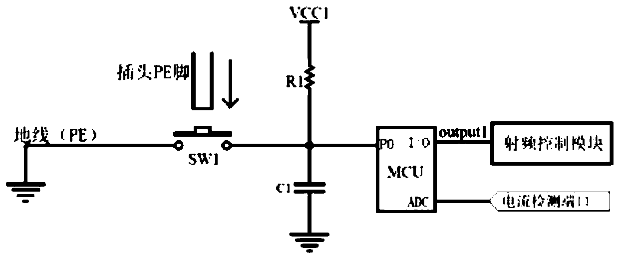
[0028] Such as figure 1 , this embodiment proposes an electric vehicle charging socket, including a socket, a trigger switch, a controller, a radio frequency communication module and a current detection module (not described in figure 1 show).

[0029] The socket includes at least one set of jacks, and each set of jacks is composed of L holes, N holes, and E holes.

[0030] In this embodiment, the trigger switch is specifically a tact switch SW1 (which can also be replaced by a shrapnel), which is located at the bottom of the E hole. When the plug is fully inserted into the socket, the PE pin of the plug presses down the button of the tact switch SW1 to close the tact switch SW1. One end of the light touch switch SW1 is connected to the ground wire PE, and the other end is connected to the high level port of the controller.

[0031] The controller MCU has a high level port P0, an output port I / O and a current detection port ADC. In addition to being connected to the tact s...

Embodiment 2

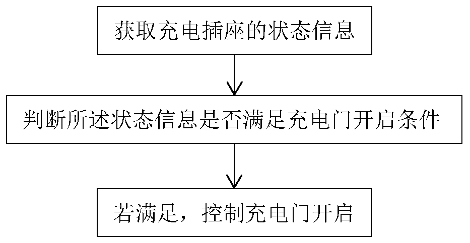
[0041] Such as image 3 and Figure 4 , the method for controlling the electric vehicle charging cover proposed in this embodiment can be realized through the electric vehicle charging socket proposed in Embodiment 1, and is the flow of the program stored and executed by the controller MCU and executed by the radio frequency communication module.

[0042] This embodiment includes the following steps:

[0043] a) Obtain the status information of the charging socket.

[0044] The status information of the charging socket includes: a level signal indicating whether the power plug of the charging gun is inserted into the charging socket or not. In this embodiment, the action of inserting the power plug of the charging gun into the charging socket triggers the change of the level signal, so that the controller can obtain the status information of the charging socket.

[0045]When the power plug of the charging gun is not inserted into the charging socket, the tact switch SW1 is ...


PUM


Abstract

The invention provides a control method of an electric vehicle charging cover and a charging socket. The charging socket comprises a plug sleeve, a trigger switch, a controller and a radio frequency communication module, wherein the trigger switch is arranged at the bottom of an E hole of the plug sleeve, when a plug is fully inserted into the plug sleeve, the trigger switch is connected, one endof the trigger switch is connected to a ground wire, and the other end of the trigger switch is connected to a high-level port of the controller; and an output port of the controller is connected withthe radio frequency communication module. The control method comprises the steps of obtaining state information of the charging socket; judging whether the state information meets a charging cover opening condition or not; and if yes, controlling the charging cover to be opened. According to the control method, charging steps of an electric vehicle is simplified, the action of "inserting the charging gun power plug into the charging socket" serves as a triggering condition for starting charging, a user does not need to manually issue an instruction for starting the charging cover, the problemthat the charging steps are tedious is solved, and the charging experience of the user can be improved.

Description

technical field [0001] The invention relates to a method for controlling a charging cover of an electric vehicle, and the IPC classification may belong to B60R16 / 02. Background technique [0002] With the popularity of electric vehicles in the world and at home, users have higher and higher requirements for the automation of electric vehicle charging. However, the current traditional way to open the charging cover is to use mechanical and electronic control. The driver needs to press the button in the car, the charging cover is mechanically opened by the electric drive spring, and it is closed manually after use. It is completely dependent on manual operation and automation. low level. Chinese patent application CN106347250A discloses a controller and method for a car charging cover, which requires the user to use a remote control key to open the charging cover, which still has insufficient intelligence and convenience. [0003] For relevant terms, refer to the national st...

Claims


Application Information

Patent Timeline
Patent Type & Authority Applications(China)
IPC IPC(8): B60L53/60B60L53/16
CPCB60L53/16B60L53/60Y02T10/70Y02T10/7072Y02T90/12Y02T90/14
Inventor 石华山洪登月
Owner JIANGMEN TIANDE ELECTRICAL APPLIANCE CO LTD
Why Eureka
Try Eureka