Eureka AIR delivers breakthrough ideas for toughest innovation challenges, trusted by R&D personnel around the world.

Rear longitudinal beam assembly for fixing torsion beam

A technology of rear longitudinal beams and torsion beams, which is applied in the field of automobile assembly, can solve problems such as the deviation of the actual value of the installation hole, the stiffness and mode of the installation point are not conducive to lifting, and the difficulty of torsion beam assembly, so as to absorb the cumulative tolerance and improve the ride. Feel the effect of reducing manufacturing costs

Pending Publication Date: 2019-12-20
ZHEJIANG UFO AUTOMOBILE MFG CO LTD +1
View PDF0 Cites 2 Cited by
  • Summary
  • Abstract
  • Description
  • Claims
  • Application Information

AI Technical Summary

Problems solved by technology

[0002] The traditional car body structure is generally divided into two types. The installation grooves on the left and right sides of the existing car body for the installation of the torsion beam are U-shaped structures, and the size of the U-shaped opening is slightly larger than the rubber bushing. Errors lead to deviations between the actual value and the theoretical value of the mounting surface and mounting holes on the vehicle body. When the rubber bushing of the torsion beam is inserted into the mounting grooves on both sides, it will be difficult to assemble the torsion beam.
[0003] The existing structural form of welding nuts on the mounting surface of the torsion beam of the vehicle body has the characteristics of simple structure and easy control of welding precision. However, since there is no cavity structure to decompose the force, the stiffness and mode of the mounting point are not conducive to lifting

Method used


Image

  • Rear longitudinal beam assembly for fixing torsion beam
  • Rear longitudinal beam assembly for fixing torsion beam
  • Rear longitudinal beam assembly for fixing torsion beam

Examples


Embodiment 1

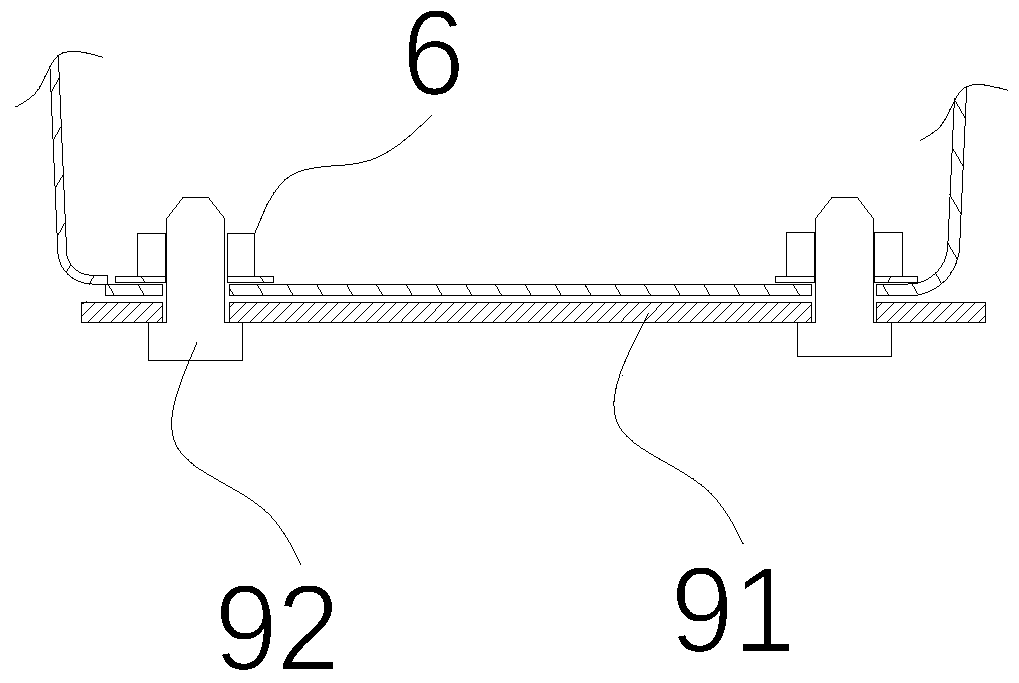
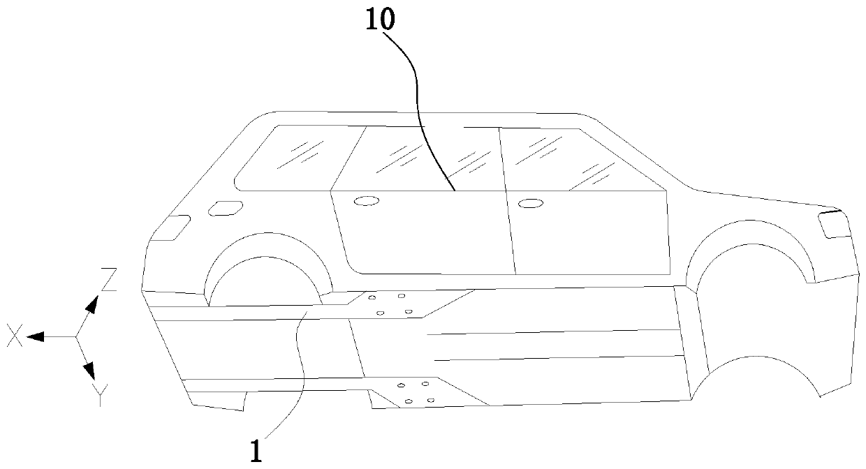
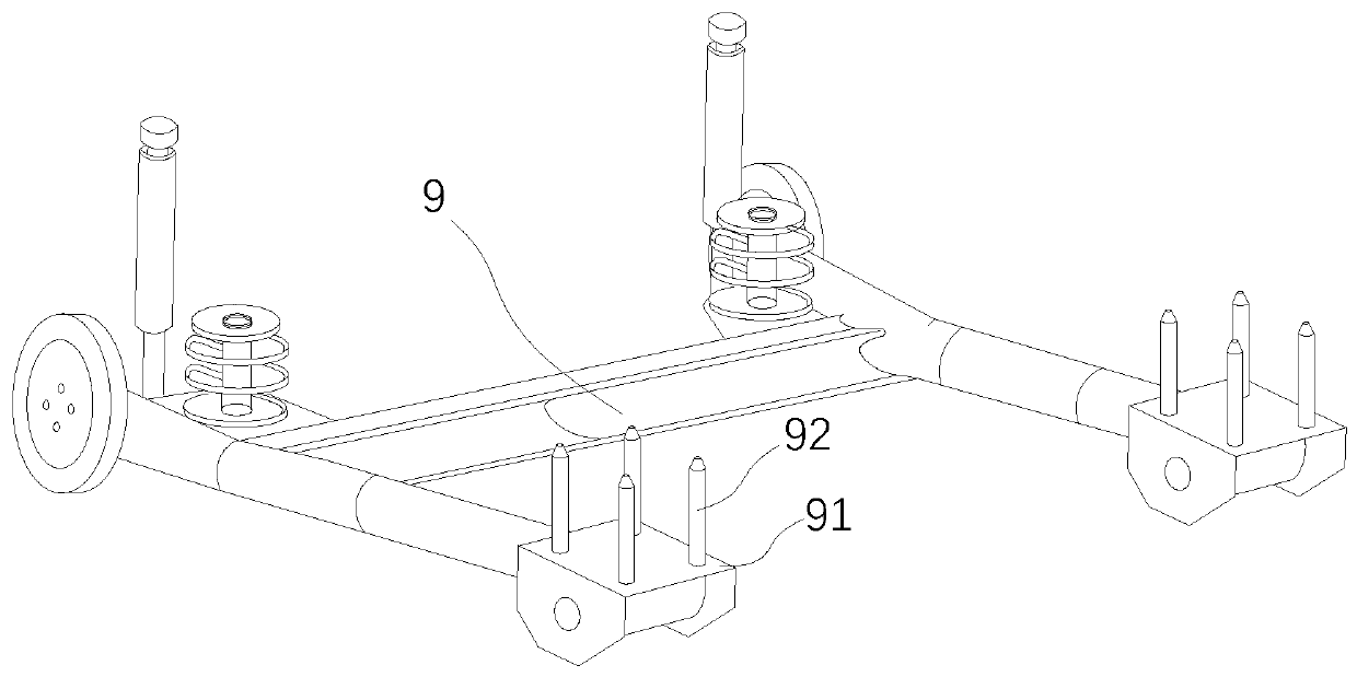
[0034] like Figure 1-Figure 11 As shown, it includes a longitudinal beam 1, a support member 2, a top cover plate 3, a side sealing plate 8, several adjusting brackets 5 and projection welding nuts 6. The longitudinal beam 1 is a ""-shaped panel and includes an integrally formed installation plane panel 11 and a vertical curved panel 12, the top cover plate 3 is fixedly connected to the top of the vertical curved panel 12, and the side sealing panel 8 is vertically arranged And both ends are respectively fixedly connected with the installation plane plate 11 and the top cover 3 to form a cavity 7 for accommodating the support 2, the top cover 3 is provided with several through holes 31, each through hole 31 Several limit holes 32 are arranged around, and the adjustment bracket 5 is provided with accommodating holes 51 for accommodating projection welding nuts 6. The support member 2 is a square-shaped cylindrical structure, and all corners of the support member 2 are provided...

Embodiment 2

[0047] like Figure 1-Figure 11 As shown, it includes a longitudinal beam 1, a support member 2, a top cover plate 3, a side sealing plate 8, several adjusting brackets 5 and projection welding nuts 6. The longitudinal beam 1 is a ""-shaped panel and includes an integrally formed installation plane panel 11 and a vertical curved panel 12, the top cover plate 3 is fixedly connected to the top of the vertical curved panel 12, and the side sealing panel 8 is vertically arranged And both ends are respectively fixedly connected with the installation plane plate 11 and the top cover 3 to form a cavity 7 for accommodating the support 2, the top cover 3 is provided with several through holes 31, each through hole 31 Several limit holes 32 are arranged around, and the adjustment bracket 5 is provided with accommodating holes 51 for accommodating projection welding nuts 6. The support member 2 is a square-shaped cylindrical structure, and all corners of the support member 2 are provided...


PUM


Abstract

The invention relates to the technical field of automobile assembly, and particularly relates to a rear longitudinal beam assembly for fixing a torsion beam. The assembly comprises a longitudinal beam, a supporting piece, a top cover plate, a side sealing plate, a plurality of adjusting supports and projection welded nuts, wherein the longitudinal beam is arranged at the section, close to the vehicle tail, of the bottom of a vehicle body, the longitudinal beam is a J-shaped face plate and is provided with an mounting flat face plate and a vertical curved face plate which are integrally formed,the side sealing plate is fixedly connected with the mounting flat face plate and the top cover plate to form a cavity for containing the supporting piece, a plurality of through holes are formed inthe top cover plate, a plurality of limiting holes are formed in the peripheries of the through holes, the adjusting supports are provided with containing holes, all corners of the supporting piece are provided with channels, and the longitudinal beam is provided with a plurality of mounting holes. According to the assembly, the rigidity and modality of a mounting part are improved, and by adjusting the movement amount of the supports, the accumulated tolerance of peripheral parts can be effectively absorbed, the number of the times of reworking are reduced, and the assembling efficiency is guaranteed.

Description

technical field [0001] The invention relates to the technical field of automobile assembly, in particular to a rear longitudinal beam assembly for fixing torsion beams. Background technique [0002] The traditional car body structure is generally divided into two types. The installation grooves on the left and right sides of the existing car body for the installation of the torsion beam are U-shaped structures, and the size of the U-shaped opening is slightly larger than the rubber bushing. Errors lead to deviations between the actual value and the theoretical value of the mounting surface and mounting holes on the vehicle body. When the rubber bushing of the torsion beam is inserted into the mounting grooves on both sides, it will be difficult to assemble the torsion beam. [0003] The existing structural form of welding nuts on the mounting surface of the torsion beam of the vehicle body has the characteristics of simple structure and easy control of welding precision. How...

Claims


Application Information

Patent Timeline
IPC IPC(8): B62D21/00B62D65/02
CPCB62D21/00B62D65/024
Inventor 陈文仙赵堃田峰荣升格朱方强万中留
Owner ZHEJIANG UFO AUTOMOBILE MFG CO LTD
Why Eureka
Eureka Blog
Learn More