Movable type counterweight device for bridge closure and use method thereof
A counterweight device and mobile technology, which is applied in bridges, bridge construction, erection/assembly of bridges, etc., can solve the problems of inflexible use, inability to ensure accuracy, complicated operation, etc., and achieve the effect of ensuring stability
- Summary
- Abstract
- Description
- Claims
- Application Information
AI Technical Summary
Problems solved by technology
Method used
Image

Examples
Embodiment 1
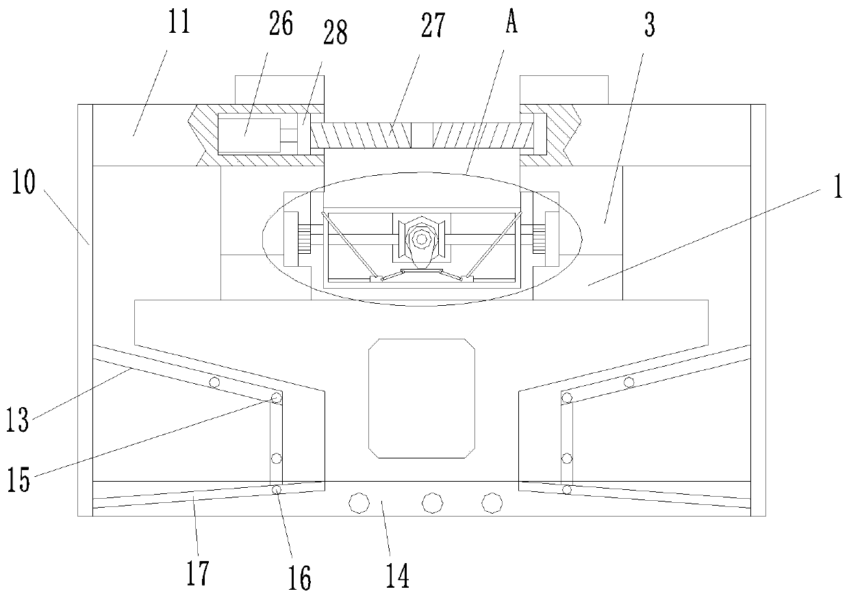
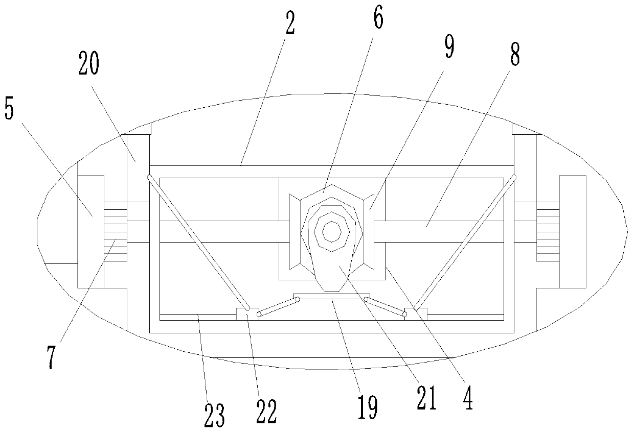
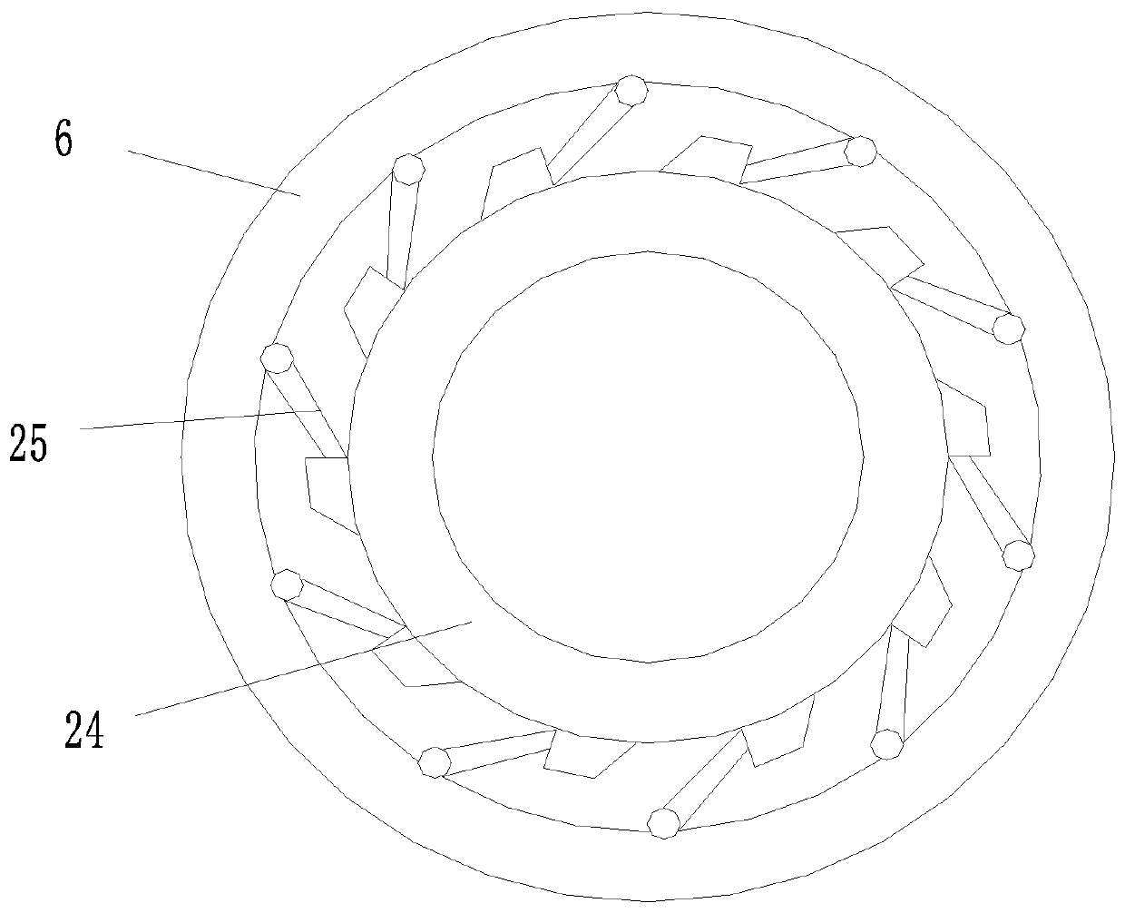
[0030] Such as Figure 1 to Figure 4 As shown, a mobile counterweight device for bridge closing includes a traveling mechanism and a counterweight mechanism. The traveling mechanism includes two parallel walking tracks 1 and a walking frame 2 between the two walking tracks 1. The two walking The track 1 is provided with brackets 3, and the two brackets 3 are respectively slidably connected to the corresponding walking track 1, and the two brackets 3 are provided with a locking structure, and the walking frame 2 is provided with a first motor 4 and a walking wheel 5. And the first transmission assembly, the output shaft of the first motor 4 is connected with the first bevel gear 6 through the first transmission assembly so that the forward fixed transmission and reverse rotation can be realized between the first bevel gear 6 and the output shaft of the first motor 4 Relatively rotating, two groups of traveling wheels 5 are respectively located on the corresponding traveling tra...
Embodiment 2
[0038] Such as Figure 1 to Figure 4 As shown, a method for using a mobile counterweight device for bridge closure, comprising the following steps,
[0039] S1. Install the walking track 1 on the bridge to be closed, adjust the levelness of the walking track 1 and fix it, install the walking frame 2 on the walking track 1, and fix and install the pouring formwork with the corresponding support seat 11 through the connecting rod 10 On the support 3 of the walking track 1;
[0040] S2. Start the first motor 4, drive the first bevel gear 6 and the cam disc 21 to rotate in the forward direction through the first motor 4, the cam disc 21 will squeeze the lifter 19 to lower, and the first connecting member pushes the slider 22 to move to the left , the second connecting piece pushes the locking piece 20 to move to the right and separates from the brake gear 7, while the first bevel gear 6 meshes with the second bevel gear 9 to drive the rotating shaft 8 and the walking wheel 5 to m...
PUM
 Abstract
Description
Claims
Application Information