Supercharge Your Innovation With Domain-Expert AI Agents!

Method suitable for industrial image detection

An image detection and industrial technology, applied in the field of industrial image detection system, can solve the problems of complex collection of industrial product images and inability to obtain complete and clear images

Inactive Publication Date: 2019-12-20
翌视智能科技(上海)有限公司
View PDF5 Cites 3 Cited by
  • Summary
  • Abstract
  • Description
  • Claims
  • Application Information

AI Technical Summary

Problems solved by technology

Such adjustment steps complicate the acquisition of images of industrial products
[0004] Although the current camera has an automatic zoom function, due to the limitation of the depth of field of the camera itself, especially in macro photography, the camera cannot obtain a complete and clear image of the object surface with a certain length through adjustment operations such as automatic zoom

Method used


Image

  • Method suitable for industrial image detection
  • Method suitable for industrial image detection
  • Method suitable for industrial image detection

Examples


Embodiment Construction

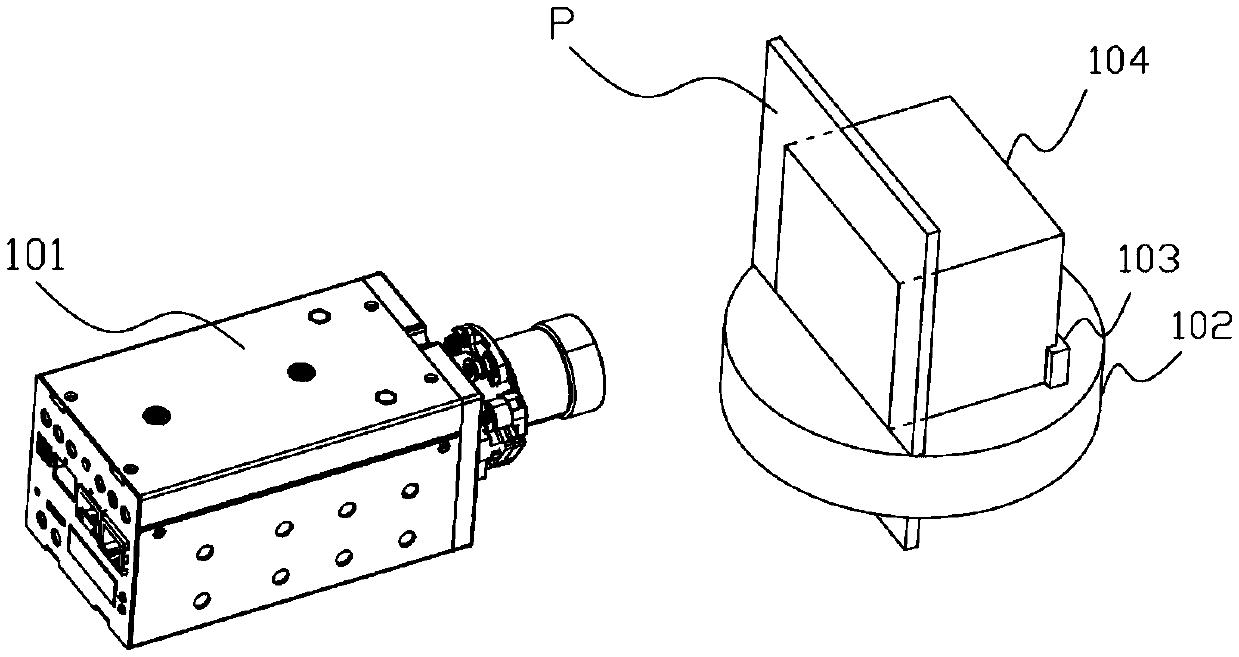
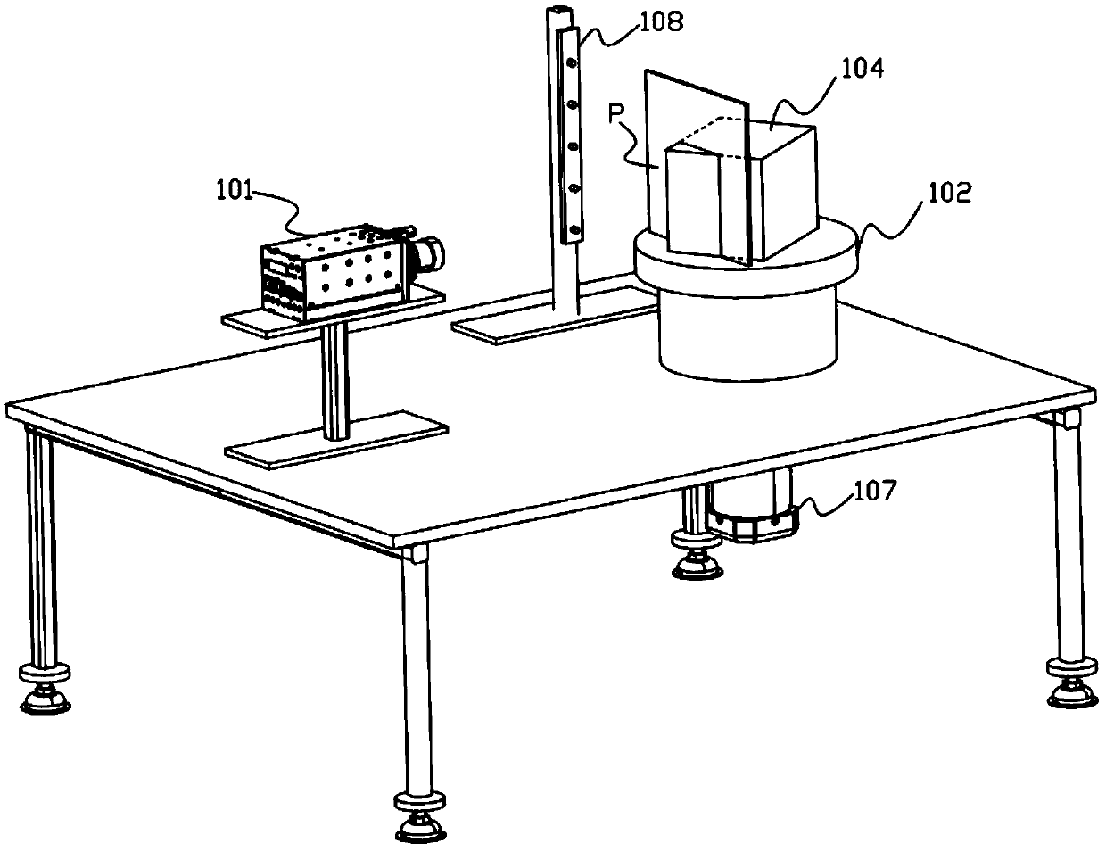
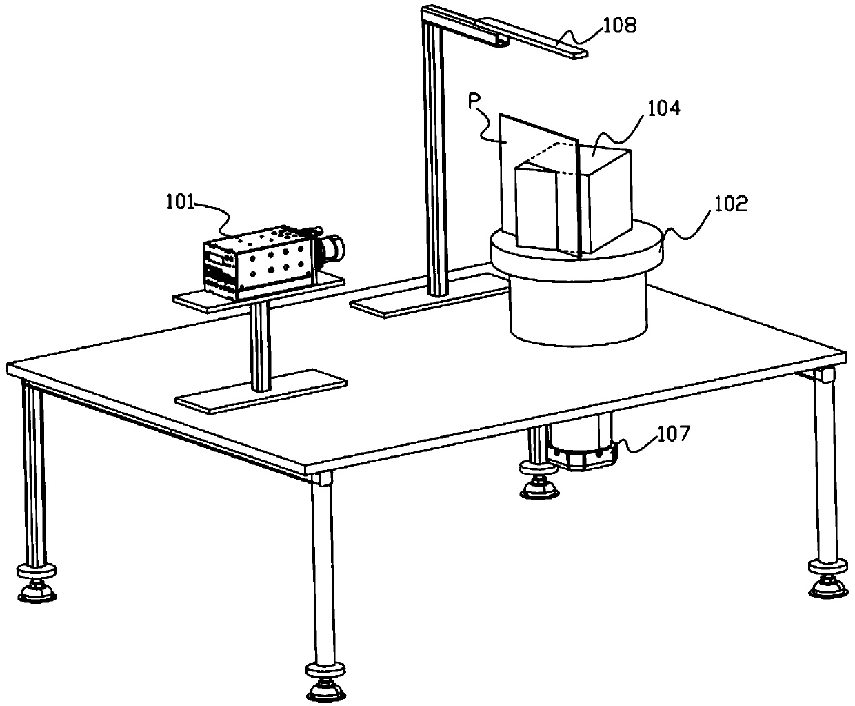
[0033] Clear imaging surface P

[0034] For an image acquisition device, such as a camera, video camera, scanner, etc., it can be known from optical principles that if the physical conditions such as the type and position of optical and electronic components in the image acquisition device are not changed, the distance and range that the camera can clearly image are often fixed. of.

[0035] Such as Figures 1A-1C As shown, the area that can be clearly photographed by the camera 101 is defined as the clear imaging plane P. Generally speaking, the shape of the clear imaging surface P depends on the hardware of the camera 101, especially the shape of the image sensor, Figures 1A-1C The example in FIG. 2 is drawn as a rectangle for illustration only, in fact, the clear imaging surface P can be in any shape. The size of the clear imaging plane P and its distance and angle from the camera 101 are determined by the relative relationship between the lens and the image sensor.

...


PUM

PropertyMeasurementUnit
wavelengthaaaaaaaaaa

Abstract

The invention relates to a method suitable for industrial image detection. The method comprises following steps of: moving a to-be-detected object on a transport plane along a transport straight lineby using a transport device; taking images of the to-be-detected object by using a plurality of offset cameras; and processing the images taken by the offset cameras so as to identify clear imaging parts in the images and using the clear imaging parts in image detection, wherein at least two offset cameras are arranged opposite so as to be at two sides of the transport straight line respectively,the offset camera comprises an imaging sensor and a lens, a sensor plane of the imaging sensor and a main optical axis of the lens intersect obliquely, so as to put a clear imaging side of the offsetcamera on a moving path of the to-be-detected object. The invention has the beneficial effect of providing an optical detection method suitable for an industrial production line. The method acquires clear images without regulating a spatial position of a to-be-tested object / camera in advance and uses the clear images in industrial detection.

Description

technical field [0001] The invention relates to an industrial image detection system and method. Background technique [0002] The detection of surface flaws in industrial products requires high precision. When manually inspecting the surface defects of industrial products, it is necessary to rely on the eyes of inspectors to carefully check the surface of industrial products, which is time-consuming and laborious. Moreover, the accuracy of detection mainly depends on uncertain factors such as workers' experience, eyesight, physical strength, etc., and cannot be applied to industrial production that requires high precision. [0003] At the same time, when collecting images of industrial products through image acquisition devices such as cameras and video cameras, it is often necessary to adjust the parameters such as the focal length and aperture of the camera or video camera or the relative direction, distance, etc. between the camera or video camera and the industrial pro...

Claims


Application Information

Patent Timeline
Patent Type & Authority Applications(China)
IPC IPC(8): G01N21/89G01N21/896G06T7/00G06T7/13
CPCG01N21/8851G01N21/8903G01N2021/8887
Inventor 张磊王玉国王天雄童磊孙叠
Owner 翌视智能科技(上海)有限公司
Features
  • R&D
  • Intellectual Property
  • Life Sciences
  • Materials
  • Tech Scout
  • Unparalleled Data Quality
  • Higher Quality Content
  • 60% Fewer Hallucinations
Learn More