
Automatic battery cell spot welding machine

A technology of spot welding machine and electric core, which is applied in the direction of resistance welding equipment, electrode characteristics, welding equipment, etc., can solve the problems of low production efficiency and high labor cost, and achieve the effect of improving efficiency, reducing labor cost and improving production efficiency

Active Publication Date: 2019-12-24
东莞市雷崴电子有限公司
View PDF9 Cites 2 Cited by
  • Summary
  • Abstract
  • Description
  • Claims
  • Application Information

AI Technical Summary

Problems solved by technology

At present, manual spot welding is usually used to process the battery cells one by one, and the metal sheets are spot welded to the two poles of the battery core respectively. This manual spot welding processing method has the problems of low production efficiency and high labor cost.

Method used


Image

  • Automatic battery cell spot welding machine
  • Automatic battery cell spot welding machine
  • Automatic battery cell spot welding machine

Examples


Embodiment Construction

[0038] The present invention will be described in detail below in conjunction with the accompanying drawings and embodiments.

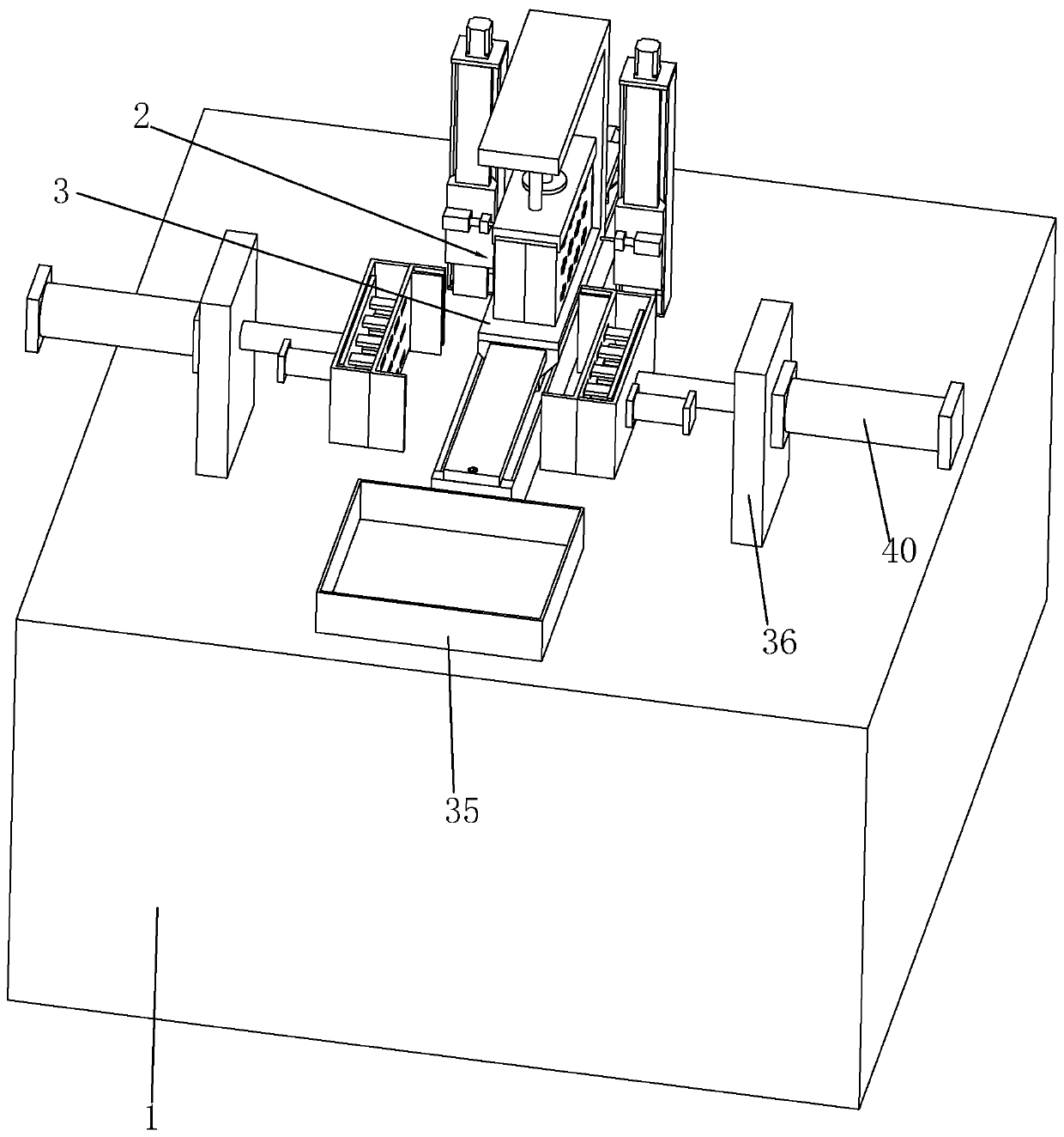
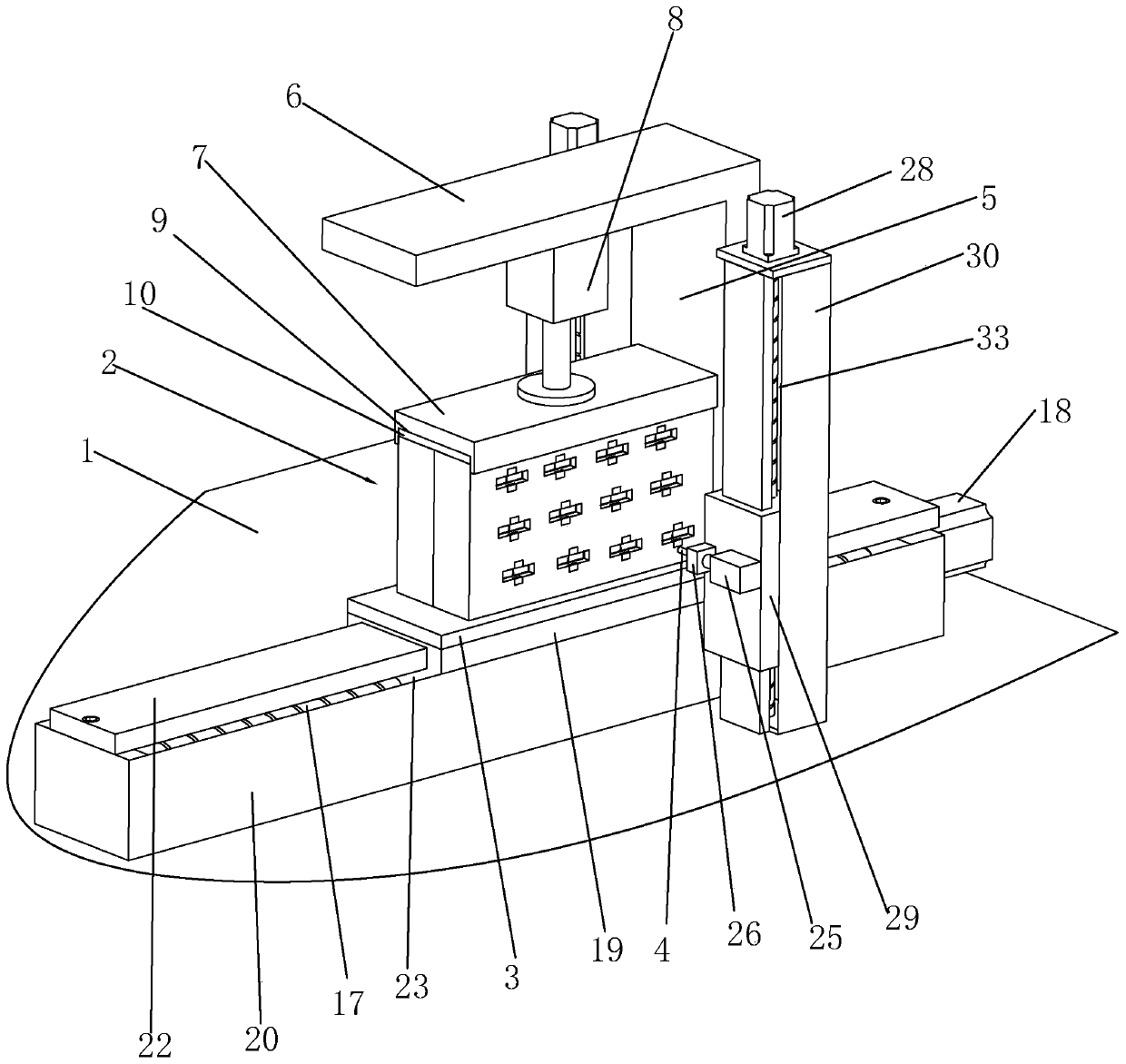
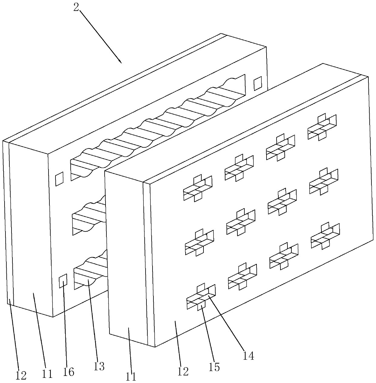
[0039] A battery automatic spot welding machine, such as figure 1 and figure 2 As shown, it includes a machine 1, a cell jig 2 for horizontally arranging multiple cells, a placement plate 3 for placing the cell jig 2, and a placement plate for pressing down and fixing the cell jig 2 3, the two electric welding heads 4 on both sides of the electric core jig 2 and the two pushing devices for respectively horizontally pushing the two electric welding heads 4 to weld the two ends of the electric core in the electric core jig 2; The table 1 is provided with a horizontal driving device for driving the placing plate 3 to move horizontally between the loading and unloading station and the welding station; the machine table 1 located on both sides of the horizontal driving device is vertically provided with two pushing devices respectively driving vertically...


PUM


Abstract

The invention relates to the field of mobile power supply production and processing equipment, in particular to an automatic battery cell spot welding machine. According to the technical scheme, the spot welding machine is characterized by comprising a machine table, a battery cell jig used for horizontally arranging and placing a plurality of battery cells, a placing plate used for placing the battery cell jig, a fixing device used for pressing and fixing the battery cell jig on the placing plate, two electric welding heads located on the two sides of the battery cell jig, and two pushing devices which respectively horizontally push the two electric welding heads to weld the two ends of the battery cells in the battery cell jig, wherein the machine table is provided with a horizontal driving device for driving the placing plate to move between a feeding and discharging station and a welding station, two vertical driving devices which respectively drive the two pushing devices to movevertically are vertically arranged on the positions, located on the two sides of the horizontal driving device, of the machine table, and the machine table is provided with a discharging device used for opening the battery cell jig for discharging. The automatic battery cell spot welding machine has the advantages of improving production efficiency and reducing labor cost.

Description

technical field [0001] The invention relates to the field of mobile power supply production and processing equipment, more specifically, it relates to an automatic battery spot welding machine. Background technique [0002] In the production and processing of mobile power supplies, it is necessary to combine single cells into a battery pack. One of the most important steps is to spot weld metal sheets on the positive and negative electrodes of multiple cells to achieve parallel expansion of batteries. At present, manual spot welding is usually used to process the cells one by one, and the metal sheets are respectively spot welded to the two poles of the cell. This manual spot welding processing method has the problems of low production efficiency and high labor cost. Contents of the invention [0003] In view of the deficiencies in the prior art, the purpose of the present invention is to provide an automatic battery spot welding machine, which has the advantages of improv...

Claims


Application Information

Patent Timeline
Patent Type & Authority Applications(China)
IPC IPC(8): B23K11/11B23K11/31B23K11/36
CPCB23K11/11B23K11/314B23K11/36
Inventor 雷红军
Owner 东莞市雷崴电子有限公司
Learn More