a hydraulic mount

A shell and inertial channel technology, which is applied to power plants, jet propulsion devices, internal combustion propulsion devices, etc., can solve the problems of limited vibration reduction effect of hydraulic mounts and inability to actively adjust the vibration reduction capability, so as to improve the vibration reduction effect and realize the The effect of vibration damping ability

Active Publication Date: 2022-01-04
安徽誉林汽车部件有限公司
View PDF11 Cites 0 Cited by
  • Summary
  • Abstract
  • Description
  • Claims
  • Application Information

AI Technical Summary

Problems solved by technology

[0003] The purpose of the present invention is to provide a hydraulic mount to solve the problem of limited damping effect of the hydraulic mount in the prior art and the inability to actively adjust the damping capacity

Method used


Image

  • a hydraulic mount
  • a hydraulic mount

Examples


Embodiment Construction

[0014] The present invention will be further described below in conjunction with the accompanying drawings and embodiments.

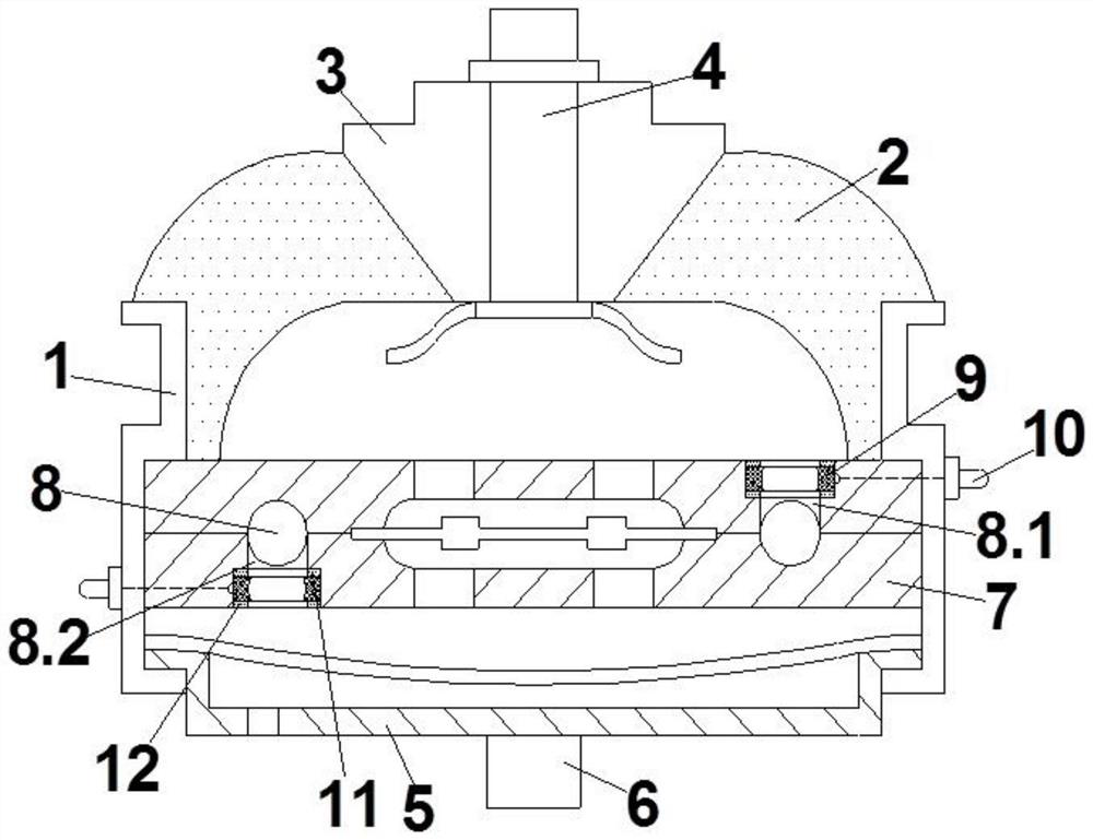
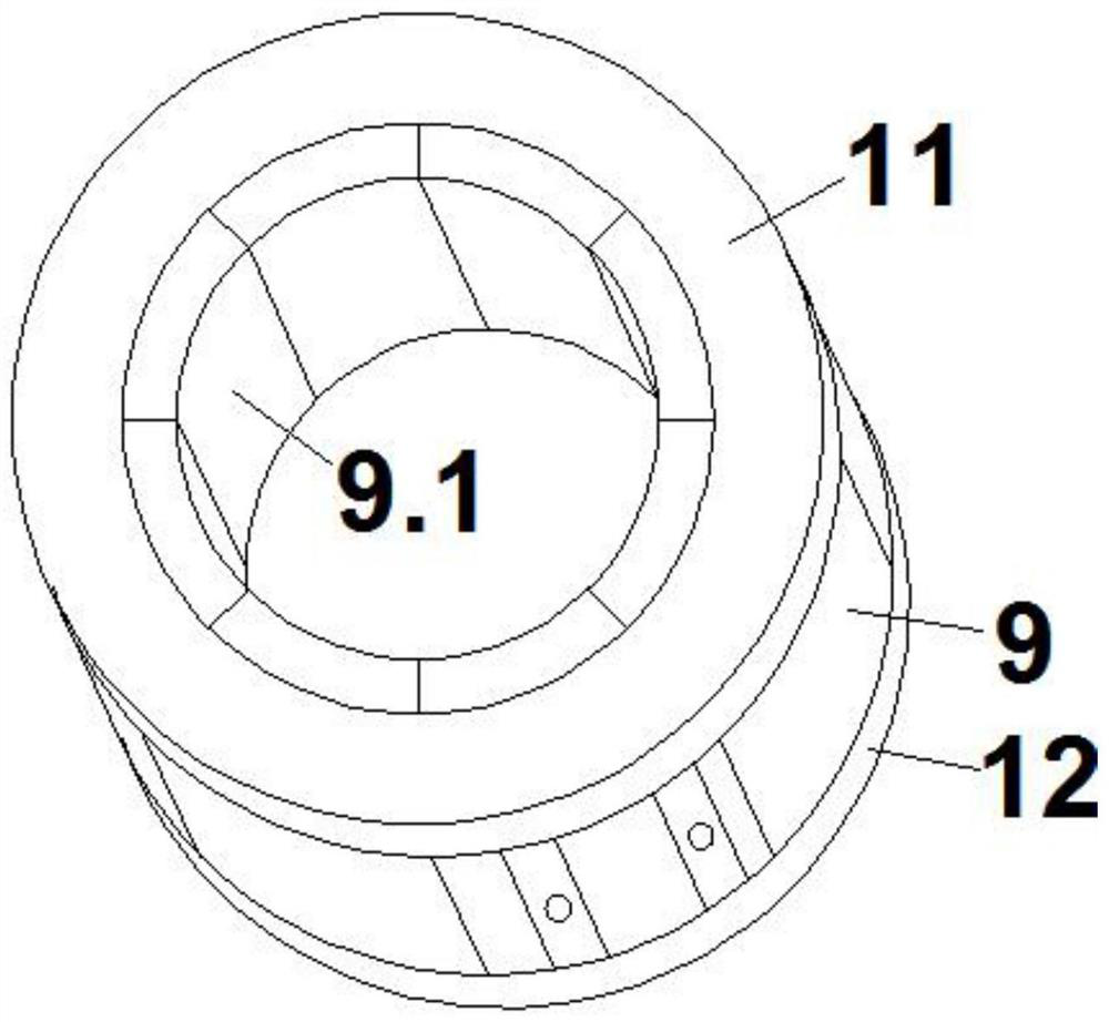
[0015] Such as figure 1 , figure 2 As shown, a hydraulic mount includes a casing 1, the upper end of the casing 1 is connected with a skeleton 3 through a rubber main spring 2, the skeleton 3 is installed with a first connecting bolt 4, the lower end of the casing 1 is connected with a base 5, and the base 5 is installed with a second Connect the bolt 6, the inner shell 1 is fixed with an inertial channel body 7, the inertial channel body 7 is provided with an inertial channel 8, one end of the inertial channel 8 is set on the upper surface of the inertial channel body 7 as the inlet port 8.1, and the other end of the inertial channel 8 is used as The outlet port 8.2 is arranged on the lower surface of the inertia channel body 7, and the magnetic fluid is used as the damping fluid in the housing 1. The inlet port 8.1 and the outlet port 8.2 of the ine...


PUM


Abstract

The invention discloses a hydraulic suspension, which comprises a casing, the upper end of the casing is provided with a rubber main spring, a frame and a first connecting bolt, the lower end of the casing is provided with a base and a second connecting bolt, an inertial channel body is fixed inside the casing, and the inertial channel body is The inertial channel is provided, the magnetic fluid is used as damping fluid in the casing, the inlet end and the outlet end of the inertial channel are respectively provided with electromagnet rings, and the electromagnet rings are electrically connected with the electrode columns on the sidewall of the casing through wires. The invention improves the damping effect and can realize the active adjustment of the damping capacity.

Description

technical field [0001] The invention relates to the field of hydraulic mounts, in particular to a hydraulic mount. Background technique [0002] The hydraulic mount is used to provide vibration-absorbing support for the automobile engine. It generally includes a casing. The upper end of the casing is fixed by a rubber main spring to the skeleton. A connecting bolt is installed on the skeleton, and another connecting bolt is installed on the lower end of the casing through the base. The connecting bolts are respectively connected to the engine shell and the bracket. The inertial channel body and the bottom film are fixed inside the shell. A decoupling plate is arranged in the middle of the inertial channel body. There is also an inertial channel in the inertial channel body. The upper surface communicates with the interior of the shell above the inertial channel body, and the outlet end of the inertial channel is located on the lower surface of the inertial channel body to co...

Claims


Application Information

Patent Timeline
Patent Type & Authority Patents(China)
IPC IPC(8): F16F13/30B60K5/12
CPCF16F13/305B60K5/1208F16F2222/12F16F2222/06
Inventor 朱林姚春生杨行愿
Owner 安徽誉林汽车部件有限公司
Why Eureka
Try Eureka