Wiring connector

A technology of connectors and wiring chambers, applied in the direction of vehicle connectors, connections, clamping/spring connections, etc., can solve the problems of inconvenient installation and achieve the effect of convenient installation

Inactive Publication Date: 2019-12-24
CHINA AVIATION OPTICAL-ELECTRICAL TECH CO LTD
View PDF10 Cites 2 Cited by
  • Summary
  • Abstract
  • Description
  • Claims
  • Application Information

AI Technical Summary

Problems solved by technology

[0004] The purpose of the present invention is to provide a wire connector, which is used to solve the problem that the nuts of the wire terminals used to connect the cables in the housing of the existing wire connector are set in the housing by interference or inlay, which leads to the problem of setting Inconvenient question

Method used


Image

  • Wiring connector
  • Wiring connector
  • Wiring connector

Examples


Embodiment Construction

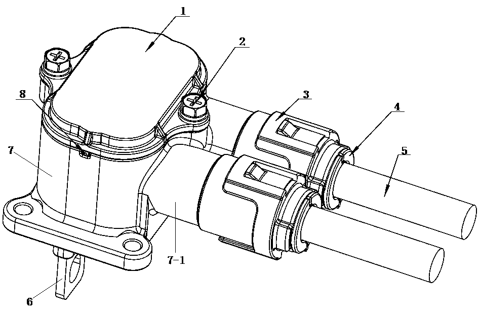
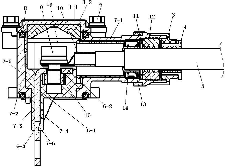
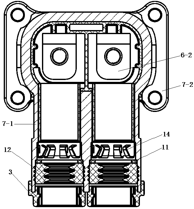
[0020] An example of the wiring connector in the present invention is Figure 1~Figure 8 As shown, it includes a base 7 and an upper cover 1 that is buckled and connected with the base 7. The base 7 and the upper cover 1 together form a wiring cavity 15. The upper cover 1 includes an upper cover housing 1-1 and an upper cover housing 1. The upper cover insulator 1-2 in -1, the base 7 includes a base shell 7-2 and a base insulator 7-5 arranged in the base shell 7-2, wherein the base shell 7-2 includes an integrally formed front and rear The base cylinder 7-1 extending in the direction, the base cylinder 7-1 communicates with the wiring cavity 15, the inner hole of the base cylinder 7-1 forms a threading hole for the cable 5 to pass through, so that the cable 5 end The connection terminal 10 protrudes into the connection cavity 15 from the back to the front.

[0021] The base insulator 7-5 is provided with a wiring nut installation hole, and a wiring nut 16 is arranged in the w...


PUM


Abstract

The invention provides a wiring connector which comprises a base and an upper cover. The base and the upper cover together form a wiring cavity. The cavity wall of the wiring cavity is provide with athreading hole for a cable to pass through. The wiring connector further comprises an L-shaped wiring insert sheet. The first bent edge of the L-shaped wiring insert sheet protrudes out of the wiringcavity to form an external wiring terminal. The second bent edge is located in the wiring cavity and is connected with the cable wiring terminal at the end of the cable. A wiring nut mounting hole isarranged in the inner side of the second bent edge in the base. A wiring nut which matches a wiring screw to clamp the cable wiring terminal and the second bent edge is arranged in a wiring nut mounting hole in a standstill manner. The base is provided with a stop structure which is in stopping fit with the L-shaped wiring insert sheet to enable the second bent edge to stop the wiring nut in the wiring nut mounting hole. By restricting the position of the L-shaped wiring insert sheet, the position of the wiring nut is restricted. The wiring nut is arranged in the base without taking other fixing measures on the wiring nut, so that the setting is very convenient.

Description

technical field [0001] The invention relates to a wiring connector. Background technique [0002] The wiring connector is a common connector on electric vehicles. It generally includes a base and an upper cover that is buckled and connected to the base. The base and the upper cover together form a wiring cavity. The cavity wall of the wiring cavity has holes for cables to penetrate Threading hole, the wiring cavity is provided with an L-shaped wiring copper bar with one end passing through the connector housing. In order to facilitate the connection between the wiring copper bar and the cable, generally a terminal is provided at the end of the cable. and terminals are fixed together by screws and nuts. [0003] For example, the Chinese utility model patent with the authorized announcement number CN204793377U discloses a plug and socket integrated waterproof connector (that is, a wiring connector), including a waterproof box, an electrical connector, and a cable, and the wat...

Claims


Application Information

Patent Timeline
Patent Type & Authority Applications(China)
IPC IPC(8): H01R13/502H01R13/512H01R13/52H01R13/648H01R13/424H01R13/02H01R4/30
CPCH01R4/30H01R13/02H01R13/424H01R13/502H01R13/512H01R13/5202H01R13/5208H01R13/648H01R2201/26
Inventor 岳梦龙娄鹏李璞郭辉
Owner CHINA AVIATION OPTICAL-ELECTRICAL TECH CO LTD
Why Eureka
Try Eureka