
Distance measuring system and method, and robot system using same

A technology of distance measurement and distance, which is applied in the field of robot systems, can solve the problems of expensive methods and achieve the effect of reliable interference

Pending Publication Date: 2019-12-27
ABB (SCHWEIZ) AG
View PDF4 Cites 0 Cited by
  • Summary
  • Abstract
  • Description
  • Claims
  • Application Information

AI Technical Summary

Problems solved by technology

[0004] The necessary multiplication of sensors makes such an approach expensive and can also create problems in the case of placing sensors, since double the cables are required and double the implemented hardware has to be synchronized

Method used


Image

  • Distance measuring system and method, and robot system using same
  • Distance measuring system and method, and robot system using same
  • Distance measuring system and method, and robot system using same

Examples


Embodiment Construction

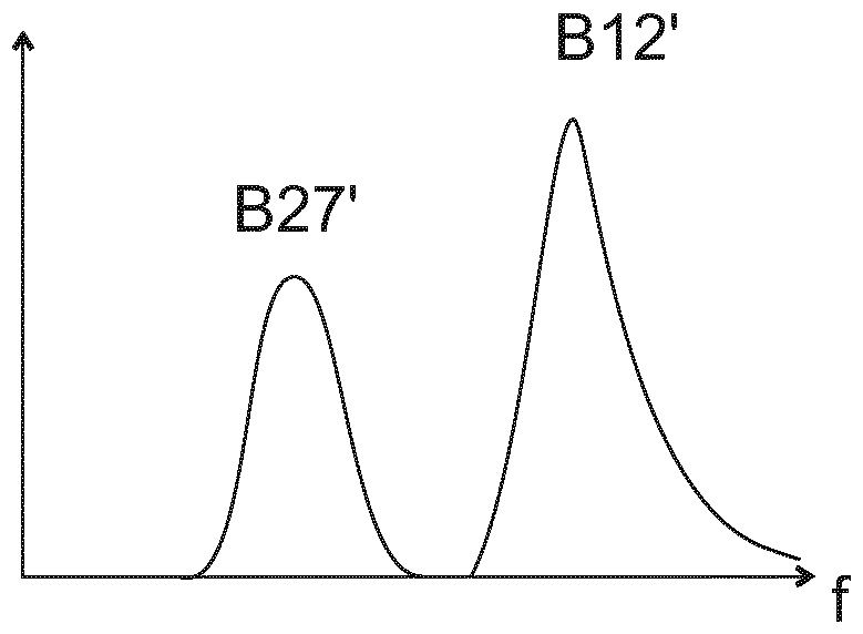
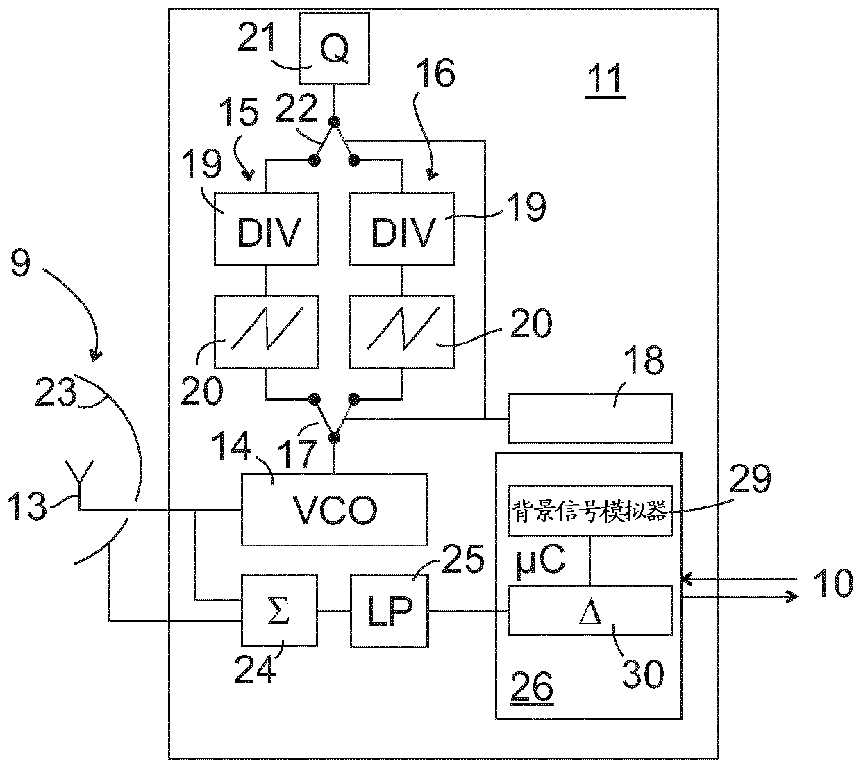
[0031] figure 1 A robot system according to the invention is shown schematically and by way of example only. The robot arm 1 comprises at least two arm elements 2 , 3 , which are connected to each other or to a tool 8 (for example grippers) via joints 4 , 5 , 6 which are pivotable via motors, preferably respectively in two degrees of freedom, to a base 7 . The transmitter-receiver unit 9 of the distance measuring system can be installed at any position of the robot arm 1; figure 1 Such a transmitter-receiver unit 9 is shown at the joint 6 between the arm element 3 and the tool 8 on the distal side; further transmitter-receiver units 9 may be used as in figure 1 It is distributed along the arm element 3 as shown by the dashed line. The joint 5 and the proximal arm element 2 (although not shown in the figures) can be equipped with a transmitter-receiver unit 9 in a corresponding manner in order to monitor over their entire length for a possible collision with an object Robot...


PUM


Abstract

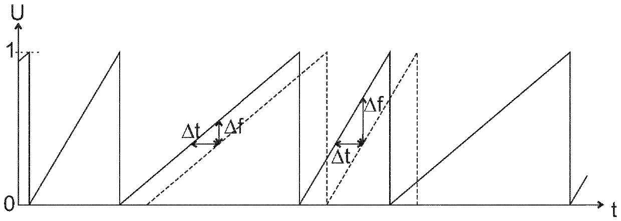
A distance measuring system comprises a transmitter (13), which emits a frequency-variable scanning signal, in particular radar signal, a receiver (23) and an evaluation unit (11) for calculating a distance to an object (12, 27) that reflects the scanning signal on the basis of a difference ([delta]f) between the frequencies of the emitted scanning signal and the received scanning signal. The rateof change of the frequency of the scanning signal has a first finite value (I) in a first operating mode of the distance measuring system and a second finite value (II) in a second operating mode. The evaluation unit (11) is configured to calculate a first distance (r1) on the basis of a frequency difference ([delta]f1) determined in the first operating mode, to calculate a second distance (r2) on the basis of a frequency difference ([delta]f2) determined in the second operating mode and to assess the correspondence between first and second distances.

Description

technical field [0001] The invention relates to a distance measuring system, a distance measuring method and a robot system in which these can be used. Background technique [0002] In order for a robot to be able to cooperate with a human employee, it is decisively important that objects with which the robot may collide during its movement are reliably detected and that the movement of the robot can be stopped in good time or at least be slowed down to such an extent. Slow, i.e. employee injuries due to robot movements can be reliably ruled out. The requirements that a robotic system has to meet in order to be considered safe in this respect are defined in standards such as ISO 13849-1:2015, ISO 10218-1:2011 or ISO 10218-2:2011 and require the following, i.e. for A malfunction of the sensor detecting the approach of the robot to a person must be reliably detectable so that the robot can be stopped in the event of a fault. [0003] One possibility for detecting functional ...

Claims


Application Information

Patent Timeline
IPC IPC(8): G01S7/40B25J9/16G01S13/34G01S13/88
CPCG01S7/4004G01S13/343G01S13/345G01S13/881B25J9/1694B25J13/088G01S7/352G01S13/584
Inventor B.马蒂亚斯R.罗伯茨A.德克C.拜纳N.莱门特
Owner ABB (SCHWEIZ) AG
Learn More