A method and device for continuous casting of metals

An equipment and metal technology, applied in the field of equipment for continuous metal casting, can solve the problems of uneven thickness of slag, slag subsidence, and unbalanced flow rate of mold

Inactive Publication Date: 2007-01-10
ABB (SCHWEIZ) AG
View PDF4 Cites 0 Cited by
  • Summary
  • Abstract
  • Description
  • Claims
  • Application Information

AI Technical Summary

Problems solved by technology

Higher velocities at the meniscus will result in: (a) sinking of the slag; (b) non-uniform slag thickness; (c) non-uniform shell thickness; and (d) risk of crack formation
[0005] In addition, oscillatory flow can cause an unbalanced flow rate downward in the crystallizer

Method used


Image

  • A method and device for continuous casting of metals
  • A method and device for continuous casting of metals
  • A method and device for continuous casting of metals

Examples


Embodiment Construction

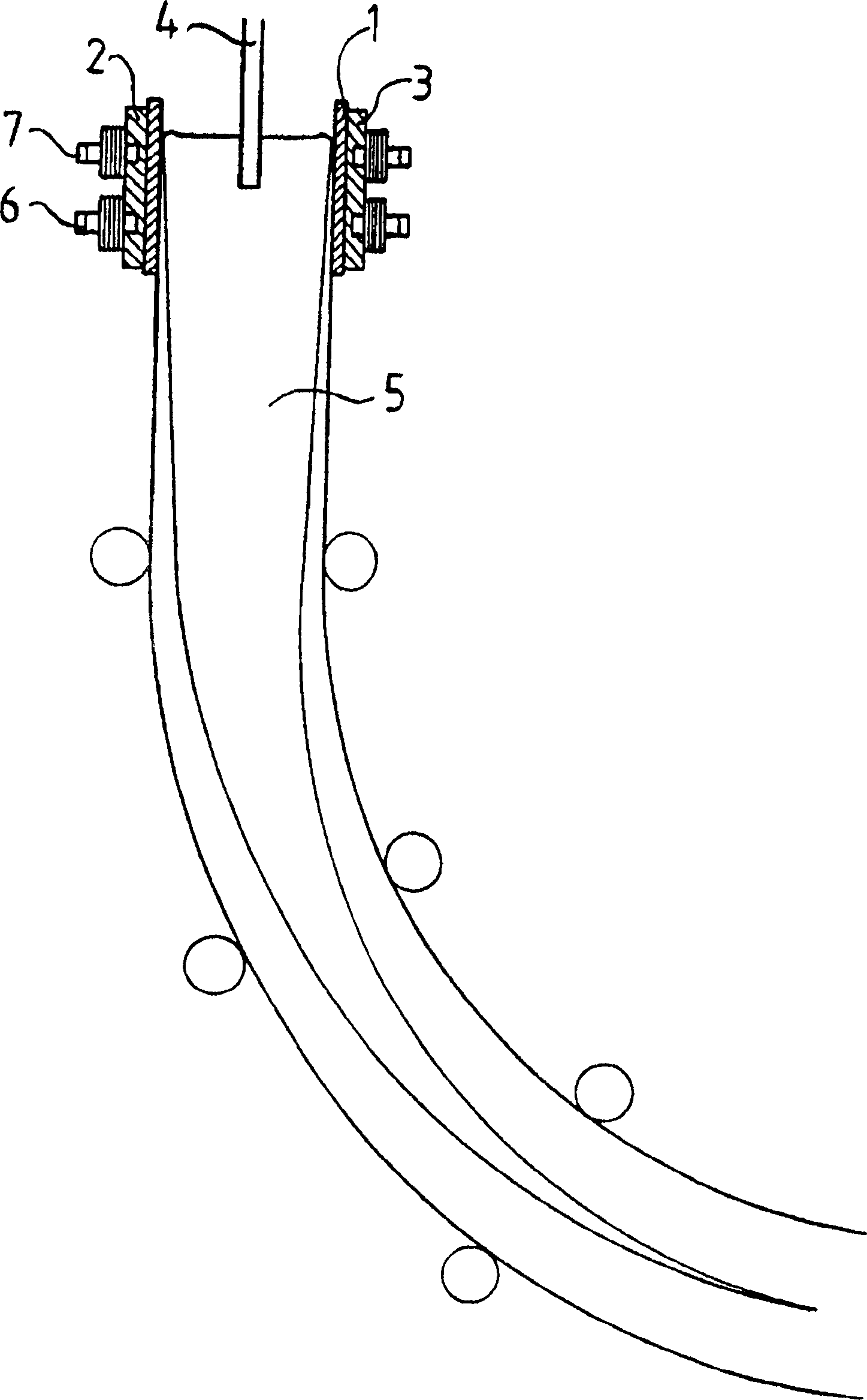
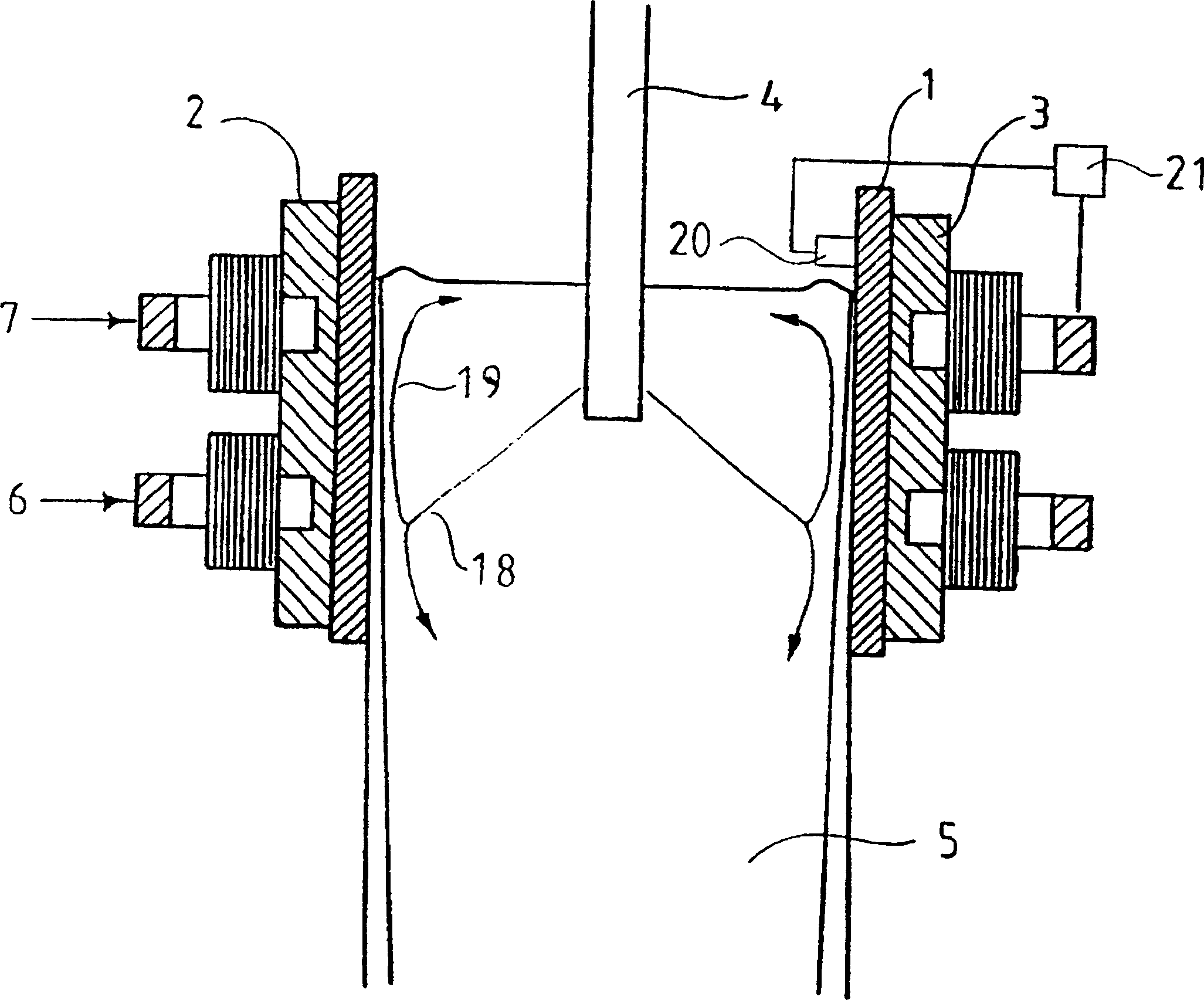
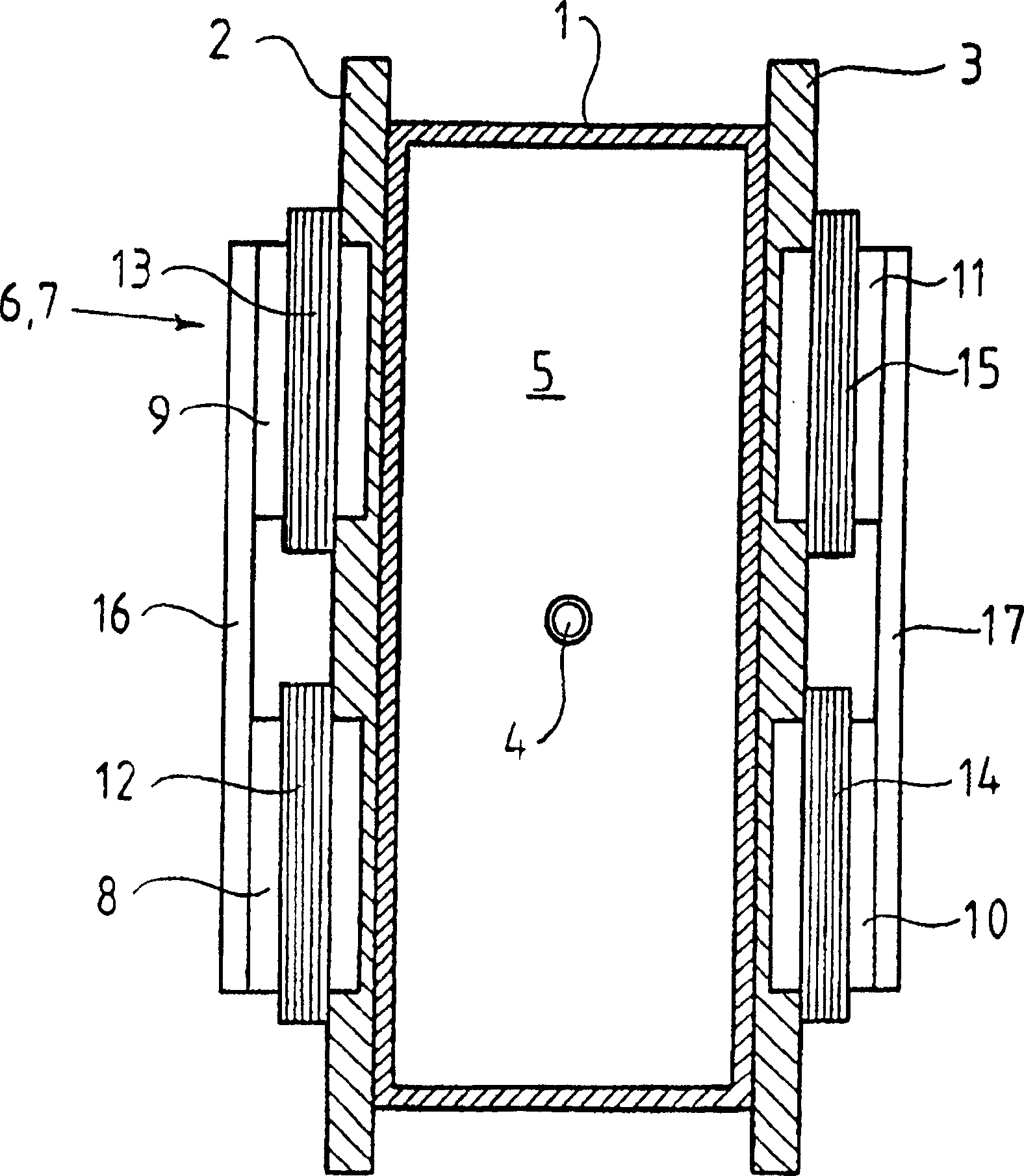
[0033] Figure 1-3 An apparatus for continuously pouring metal, such as steel, is shown. The apparatus includes a crystallizer defining a cylinder formed by four opposing walls. The crystallizer is preferably made of a copper alloy or other alloy with suitable thermal conductivity and thermal resistance. On the outside of at least two opposing walls of the crystallizer 1 are arranged elements 2 , 3 for cooling the walls. The cooling elements 2, 3 may comprise any type of support frame through which cooling channels for conveying a cooling medium, such as water, may be arranged. The channels may be arranged in such a way that the cooling medium flows directly towards the outer surface of the wall to cool the wall.

[0034] The device also comprises an element 4, a so-called "submerged nozzle (SEN)", by means of which a liquid metal can be fed from a container (not shown) to the within the space. During pouring, the crystallizer 1 is filled with metal. The metal is mainly ...


PUM


Abstract

A method and a device for continuous casting of metals, in which the device comprises a mould (1), through which a liquid metal passes, and a member (4), through which a liquid metal is supplied as a jet to the mould (1). The device comprises magnet members (6, 7) for applying a magnetic field varying with time and being substantially fixed in the room to the liquid metal in the mould (1).

Description

technical field [0001] The invention relates to a method for the continuous casting of metal, in which liquid metal is fed as a jet into a mold already filled with liquid metal. The invention also relates to a plant for the continuous casting of metal, said plant comprising a mold through which liquid metal passes during casting and an element through which liquid metal is fed as a jet to In the crystallizer already filled with liquid metal. Background technique [0002] During the continuous pouring of liquid metal fed into a mold, the liquid metal cools in the mold and forms an elongated strand. Depending on the dimensions of the cross section, the strand may be called a "bloom", "billet" or "slab". During the pouring process, the first stream of hot liquid metal is conveyed into a cooled mold in which the metal is cooled and at least partially solidified to form an elongated strand. The cooled and partially solidified strand leaves the mold continuously. The mold has ...

Claims


Application Information

Patent Timeline
IPC IPC(8): B22D11/115B22D11/04B22D11/11
CPCB22D11/115
Inventor C·斯万T·克龙J·-E·埃里克松G·塔尔贝克
Owner ABB (SCHWEIZ) AG
Why Eureka
Try Eureka