Electronic component feeder and electronic component feeding method

A technology for supplying electronic components and components, applied in the direction of electrical components, electrical components, etc., can solve problems such as unfavorable lifting, inability to perform component installation, and large lifting of the component supply plate 552

Inactive Publication Date: 2006-06-14
PANASONIC CORP
View PDF0 Cites 10 Cited by
  • Summary
  • Abstract
  • Description
  • Claims
  • Application Information

AI Technical Summary

Problems solved by technology

Since the pallet generally does not have a symmetrical structure in the length direction, the pallet placed upside down cannot perform its function, and this causes a problem that the electronic component feeder cannot be properly handled, possibly causing damage to the constituent parts of the feeder and the dispersion and damage of electronic components arranged on the tray, etc.
[0006] However, the above-mentioned structure has a problem in that although it is possible to prevent the pallet from being loaded in the direction opposite to the length direction, when the pallet is correctly loaded in the length direction, it can be detected even if the pallet is loaded obliquely in the silo ( or to prevent) misplaced
In this case, it is difficult for an operator concentrating on the electronic components to notice the inclined pallet insertion
In addition, there is a problem that since the number of pallets to be loaded into the bin increases, that is, the number of pallets decreases according to the size and thickness of electronic components to be mounted, and the number of pallets further increases according to the variety of types of electronic components, the operator makes mistakes. Increased likelihood of what happens when pallets are placed at an angle
Therefore, in the case where the suction nozzle disadvantageously sucks and holds, for example, a portion of the electronic component 551 that is not set on the component supply tray 552, when each of the electronic components 551 set on the component supply tray 552 is sucked and held by

Method used


Image

  • Electronic component feeder and electronic component feeding method
  • Electronic component feeder and electronic component feeding method
  • Electronic component feeder and electronic component feeding method

Examples


no. 1 example

[0138] A first embodiment of the present invention will be described in detail below with reference to the drawings.

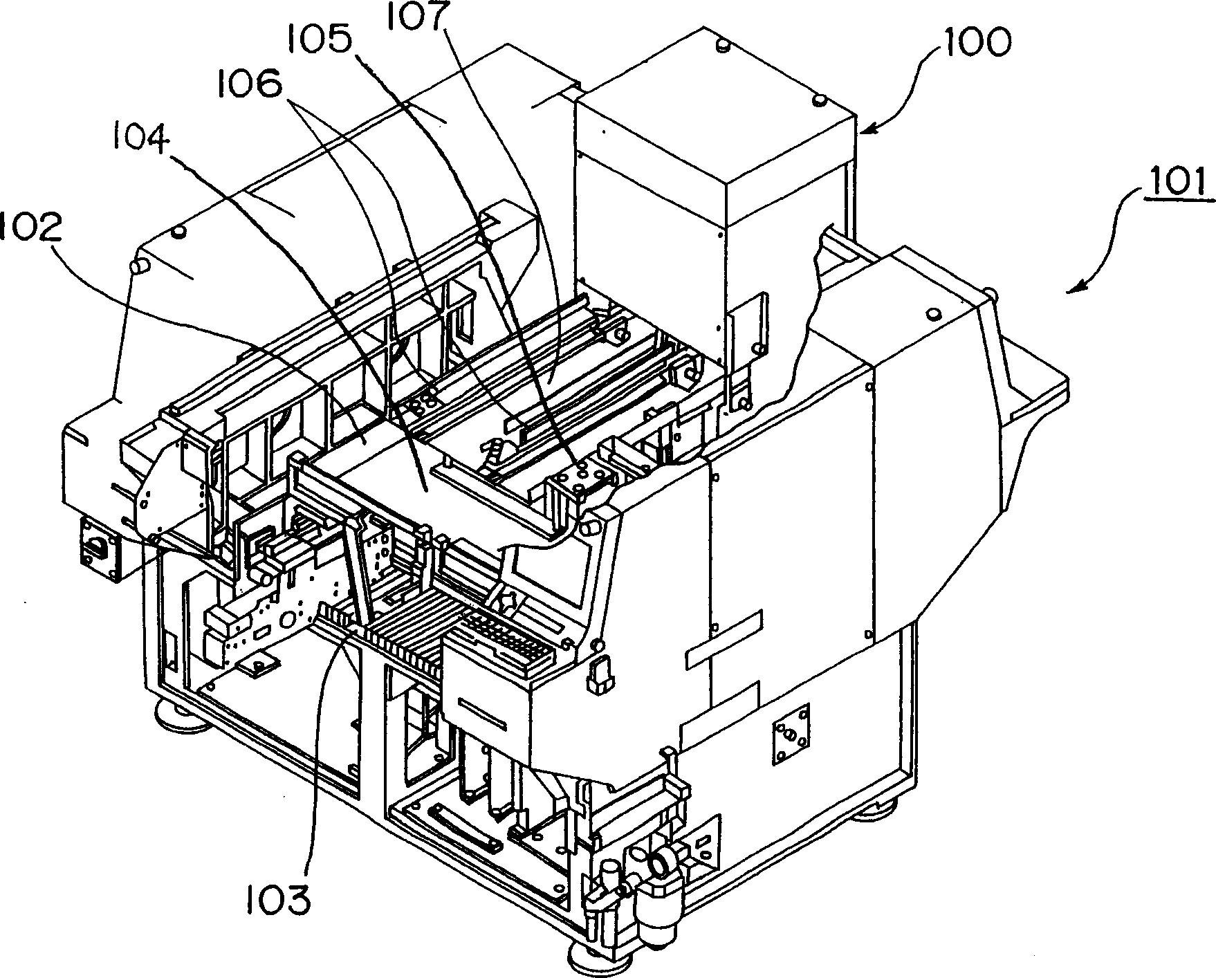
[0139] figure 1 An external perspective view (partially shown transparently) of the electronic component mounting apparatus 101 provided with the electronic component feeder 100 according to the first embodiment of the present invention is shown.

[0140] Such as figure 1 As shown in , an electronic component mounting apparatus 101 that performs component mounting to mount a plurality of supplied electronic devices on a circuit board is provided with an electronic component feeder 100 (which may be referred to as a tray component feeder) for supplyable A plurality of electronic components arranged in a line are accommodated on removable trays on the illustrated rearward side of the machine base 102 of the electronic component mounting apparatus 101; a tape-carried component feeder is also provided 103 , for supplying a plurality of tape-carried electronic ...

no. 2 example

[0195] The present invention is not limited to the above-described embodiments, but allows various other implementations. For example, it will be described below with respect to the second embodiment of the present invention that stable and efficient implementation can be performed by modifying the method for fixing a component supply tray on a pallet in an example of a pallet in the electronic component feeder 100 of the first embodiment. An electronic component feeder with a tray plate structure that prevents electronic components from jumping out of the component supply tray, etc. or an electronic component feeder with another structure.

[0196] 13A shows a plan view of a tray plate 503 of an example of a placement section in which a component supply tray (also an example of a tray) handled in an electronic component feeder according to a second embodiment of the present invention is placed, and Figure 13B Its side view is shown. also, Figure 14A A plan view showing a ...

example

[0225] first, Figure 17 A schematic sectional view of, for example, the X-axis fixing rod 524 according to the first modified example of the second embodiment of the present invention is shown. Such as Figure 17 As shown in , the X-axis fixing bar 524 is provided with a horizontal direction fixing surface 524a serving as an example of a first direction fixing portion and also serving as an example of a first direction fixing surface for passing the The end portion 502a of the tray 502 contacts the placement position of the component supply tray 502 fixed in the direction along the surface of the tray placement surface 504, and a vertical direction fixing spring (an example of a pusher) 524c serves as an example of a second direction fixing portion, Also serves as a second direction fixing surface for fixing placement of the component supply tray 502 in a direction perpendicular to the tray placement surface 504 by contact with the upper portion of the end portion 502a of th...


PUM


Abstract

The invention provides a forward side adjuster (18) for adjusting the support position of a pallet loaded in a bin (4) on the forward side in the pallet feeding direction (A); an adjustment member (24), movable in said direction, for adjusting the support position of the pallet adjusted by the forward side adjustment member on the rearward side in said direction; and a horizontal attitude adjustment member (26), which can Provided between the pallets for adjusting the supporting posture of the pallets so as to maintain a substantially horizontal supporting posture of the pallets supported by the pair of supports with the arrangement.

Description

technical field [0001] The present invention relates to an electronic component feeder and an electronic component supply method for supplying a plurality of electronic components aligned in a line on a component supply tray to mount the components on a board. Background technique [0002] Conventionally, various structures of such electronic component feeders are known. In this type of electronic component feeder, multiple pallets are loaded, stacked in layers (or stacked in rows) in a magazine, where on said pallets are placed components often used for electronic component-to-electronic component mounting A component supply tray (hereinafter referred to as a tray) of the supply system of the equipment. The electronic component feeder utilizing such a conventional magazine is configured to move the magazine up and down in the vertical direction or in the direction in which the pallets are stacked by the lifting unit, place the selected pallet in the pallet unloading positi...

Claims


Application Information

Patent Timeline
IPC IPC(8): H05K13/02
Inventor 远藤忠士城户一夫内田英树奥田修垣田信行
Owner PANASONIC CORP
Why Eureka
Try Eureka