
Industrial air purification equipment

A kind of air purification equipment and industrial technology, applied in the direction of chemical instruments and methods, dispersed particle separation, combined devices, etc., can solve the problems of unrealistic, poor purification effect, low power, etc.

Inactive Publication Date: 2019-12-31
南安新笙活商贸有限公司
View PDF0 Cites 0 Cited by
  • Summary
  • Abstract
  • Description
  • Claims
  • Application Information

AI Technical Summary

Problems solved by technology

[0002] At present, industrial air purification equipment is not only dedicated to dust and odor purification equipment in factory workshops. As air quality problems become more and more serious, conventional household air purification equipment is too low in power and poor in purification effect, causing many households to use industrial grade air purification equipment. The air purifier purifies the air in the living place, and applies the industrial air purification equipment to the household field. In addition to filtering the air, it is also necessary to focus on the sustainable performance of the filter plate. The biggest difference between household and industrial use lies in the household environment. There are no chemical molecular particles produced in the industrial environment, which is how the purification equipment can increase the recyclability of the filter plate without short-term replacement of the filter plate. Although the dust in the household environment is not as large as industrial dust and has However, during long-term use, the purification efficiency will also decrease due to dust clogging the filter plate. However, the volume of industrial air purifiers is larger than that of household air purification equipment. It is obviously not good to clean the filter plate by disassembling and replacing it. Realistic approach, based on the above premise, this case developed an industrial air purification equipment to solve this problem

Method used


Image

  • Industrial air purification equipment
  • Industrial air purification equipment
  • Industrial air purification equipment

Examples


Embodiment

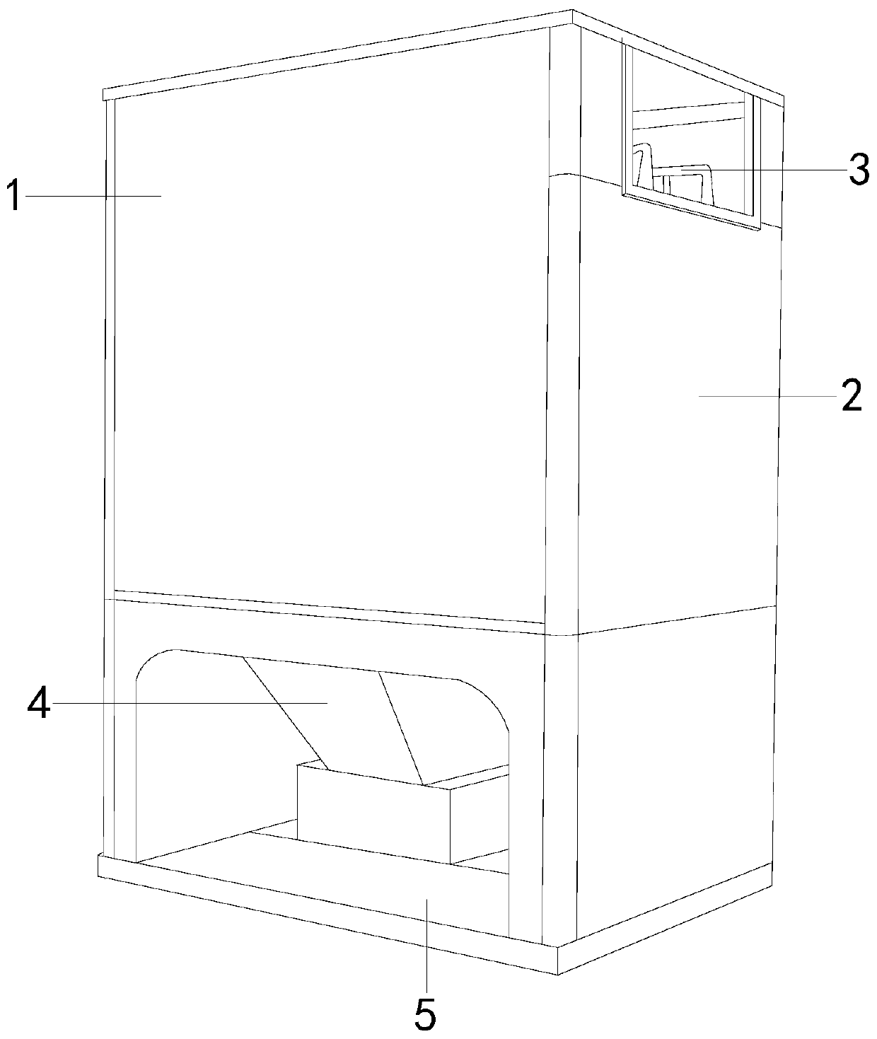
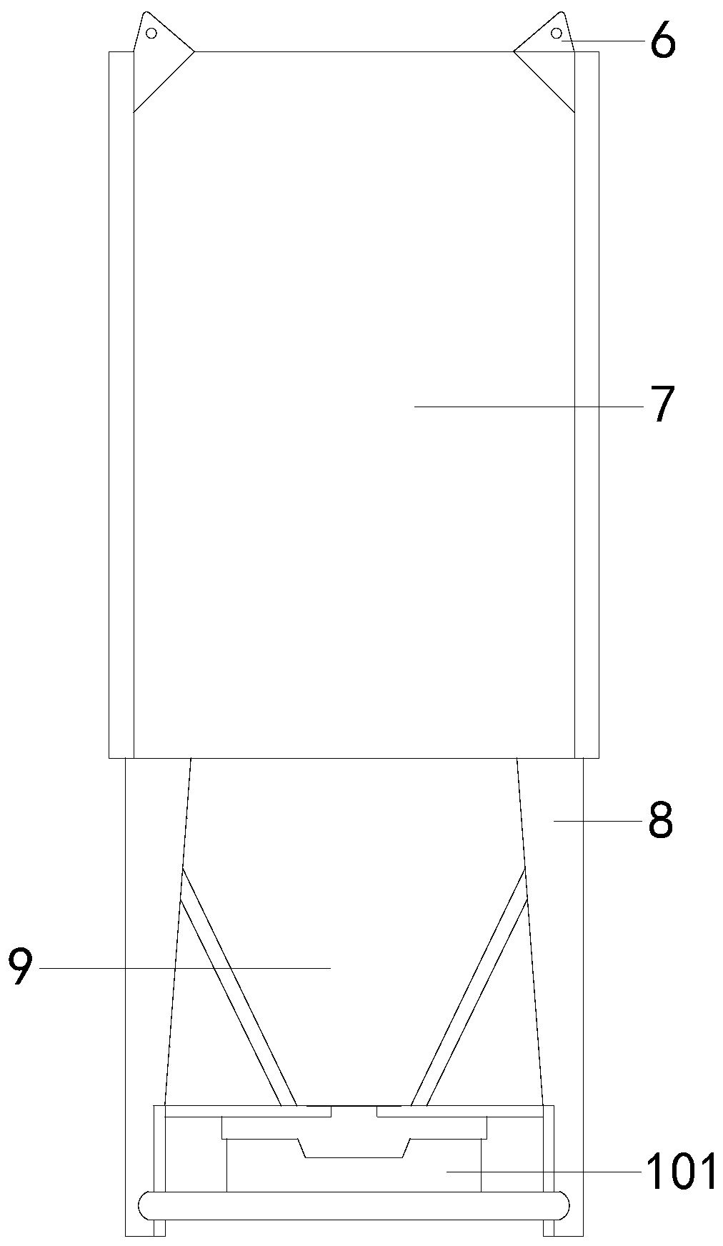
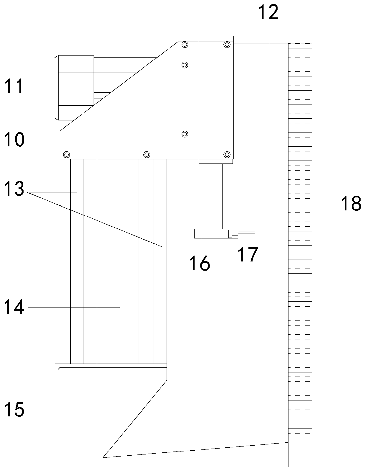
[0021] see figure 1 , the present invention provides a kind of industrial air purification equipment, its structure comprises: case shell 1, side plate 2, blower fan 3, purifying mechanism 4, base 5, described case shell 1 two sides are provided with side plate 2, side plate 2 The box shell 1 is connected to the bottom base 5, the top surface of the base 5 is connected to the purification mechanism 4, and the purification mechanism 4 is connected to the fan 3. The box shell 1 is mainly used as the main frame of the shell of the purification equipment, and at the same time plays an external role in the equipment. The protective effect of the layer prevents the equipment from being damaged by direct contact with the internal components due to impact or collision. The side plate 2 and the box shell 1 are detachable connections, which are mainly set for the daily maintenance and repair of the equipment. During maintenance, only the side plate 2 can be removed to expose the operat...


PUM


Abstract

The invention discloses industrial air purification equipment. The structure of the industrial air purification equipment comprises a box shell, side plates, a fan, a purification mechanism and a base; the beneficial effects are that: problems are solved through providing the purification mechanism with a filter plate box and a dirt collecting box. According to design, firstly, a sliding pipe structure of the filter plate box is adopted for slightly colliding on a filter plate, flapping effect is generated, so that dust on the surface of the filter plate falls; meanwhile, dust in filter holesin the filter plate is brushed away by adopting a mode that a brushing seat is directly contacted with the filter plate; when all dust falls off, a dust intercepting pipe is used for collecting and adsorbing dust floating in the air, the dust is prevented from entering the air again without being filtered to form secondary pollution, finally, the dirt collecting box is used for collecting all thedust and sewage, the purification performance and the cleaning convenience of the filter plate are effectively improved, and the filter plate does not need to be frequently disassembled, assembled andcleaned.

Description

technical field [0001] The invention relates to the field of air purification equipment, in particular to an industrial air purification equipment. Background technique [0002] At present, industrial air purification equipment is not only dedicated to dust and odor purification equipment in factory workshops. As air quality problems become more and more serious, conventional household air purification equipment is too low in power and poor in purification effect, causing many households to use industrial grade air purification equipment. The air purifier purifies the air in the living place, and applies the industrial air purification equipment to the household field. In addition to filtering the air, it is also necessary to focus on the sustainable performance of the filter plate. The biggest difference between household and industrial use lies in the household environment. There are no chemical molecular particles produced in the industrial environment, which is how the p...

Claims


Application Information

Patent Timeline
Patent Type & Authority Applications(China)
IPC IPC(8): B01D50/00
CPCB01D50/00
Inventor 陈玉兰
Owner 南安新笙活商贸有限公司
Learn More