
Energy-absorbent component

a technology of energy absorption and component, which is applied in the direction of bumpers, vehicle components, pedestrian/occupant safety arrangements, etc., can solve the problems of difficult to achieve the different impact zones transversely with respect to that direction, difficult to manufacture such a bumper, and high cost, and achieves strong stability and load-bearing structure. , the effect of good absorption

Inactive Publication Date: 2006-05-16
KAUTEX TEXTRON
View PDF14 Cites 31 Cited by
  • Summary
  • Abstract
  • Description
  • Claims
  • Application Information

AI Technical Summary

Benefits of technology

The present invention provides an energy-absorbent component for a motor vehicle that can absorb impacts with varying energy levels and protect both the vehicle and people in the vehicle. The component has a hollow body with multiple chambers filled with foam materials of different densities and strengths. The chambers can be arranged in a front-to-back manner to provide different impact zones with different energy absorption capabilities. The hollow body has a bearer that is stiff in shape and can provide a strong stable load-bearing structure. The component can be easily manufactured and can satisfy different demands in terms of people protection and motor vehicle protection. The foam materials used can be particle foams made of minibeads, which can be easily introduced into the hollow body during the blow molding process. The hollow body and the filling foam materials can be made of similar plastic materials for improved recyclability. The number and arrangement of the chambers can be varied within wide limits.

Problems solved by technology

It will be noted however that the arrangement described in EP 1 046 546 suffers from the disadvantage that the foam body which is not closed by the cover on all sides does not afford adequate stability in relation to a relatively severe impact.
That admittedly achieved a differing energy absorption capability in the direction of travel of the vehicle to which the bumper is mounted, but it will be appreciated that it is difficult to achieve differing impact zones transversely with respect to that direction.
Furthermore the manufacture of such a bumper is relatively complicated and expensive as the blow-molded bearer has to be placed in a molding tool, within which the remaining space is then filled with foam.
That arrangement is also comparatively complicated both in respect of structure and also in its manner of manufacture.

Method used


Image

  • Energy-absorbent component
  • Energy-absorbent component
  • Energy-absorbent component

Examples


Embodiment Construction

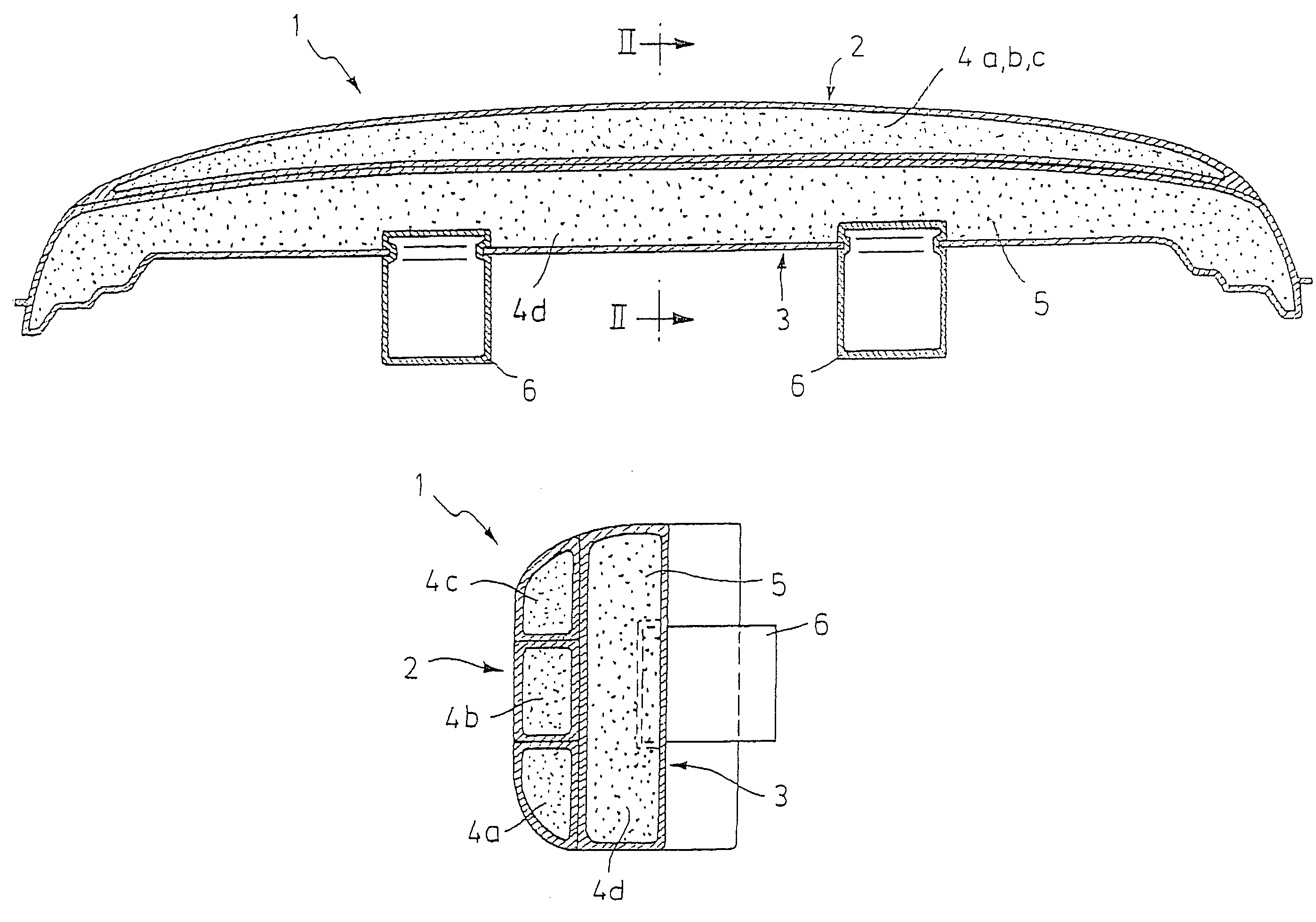
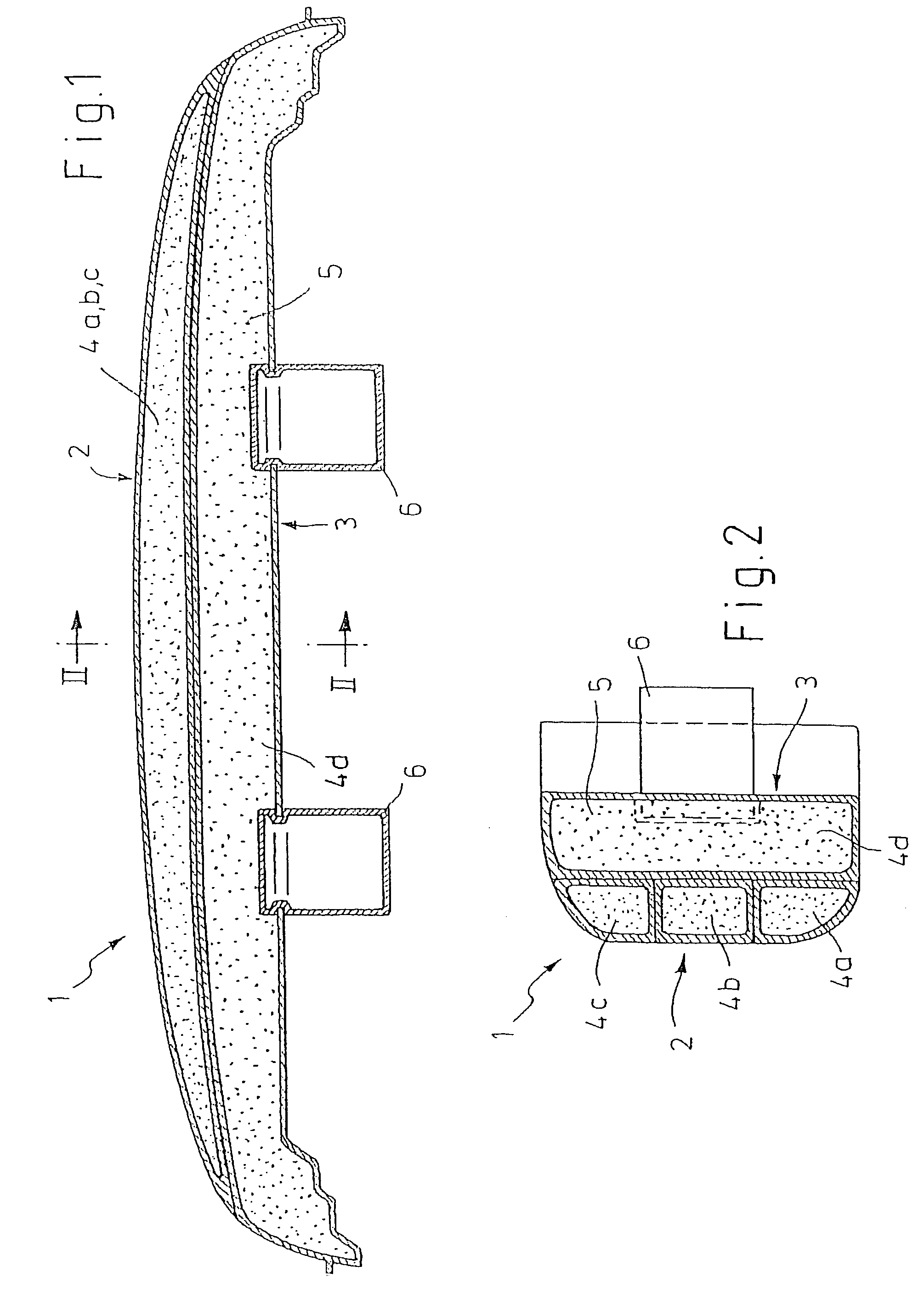
[0028]Referring to FIGS. 1 and 2, an energy-absorbent component for a motor vehicle is illustrated in the form of a bumper 1, comprising an integral plastic component produced by extrusion blow molding and obtained substantially in one operating procedure. The sectional view through the bumper 1 illustrated in FIG. 2 shows that it is in the form of a multi-chamber hollow body, as will be described in greater detail hereinafter.

[0029]It will be noted at this juncture that, for the sake of simplicity hereinafter the side of the bumper 1 which when mounted to a motor vehicle faces in the direction of forward travel of the vehicle and thus away from the engine bay or passenger compartment of the vehicle is referred to as the front side 2 whereas the side of the bumper 1 which faces towards the engine bay or the passenger compartment is referred to as the rear side 3.

[0030]Reference will be directed now more specifically to the cross-sectional view in FIG. 2 showing that the bumper 1 in ...


PUM


Abstract

Described is an energy-absorbent component for a motor vehicle, for example as a bumper, which is in the form of a blow-molded hollow body of thermoplastic material enclosing a foam filling on all sides. The hollow body comprises a plurality of chambers therein. The chambers are each closed in themselves and they each respectively accommodate a foam filling affording a differing energy absorption capability.

Description

CROSS-REFERENCES TO RELATED APPLICATIONS[0001]This application claims the priority of German patent application Ser. No. 10 2004 013 370.0 filed Mar. 17, 2004, the subject-matter of which is incorporated herein by reference.FIELD OF THE INVENTION[0002]The invention concerns an energy-absorbent component for a motor vehicle, for example as a bumper.BACKGROUND OF THE INVENTION[0003]An energy-absorbent structure which typically comprises a blow-molded hollow body of thermoplastic material which encloses a foam filling on all sides serves to absorb impact energy, the impact energy being dissipated by work done upon deformation of the structure. One consideration in that respect is that the impact energy which occurs in the event of the vehicle to which the energy-absorbent component is mounted being involved in a collision is dissipated or diverted in such a way that the vehicle itself does not suffer from permanent deformation, while a further consideration is that a vehicle bumper sho...

Claims


Application Information

Patent Timeline
Patent Type & Authority Patents(United States)
IPC IPC(8): B60R19/22B60R19/18B60R21/04B60R21/34
CPCB60R19/22B60R2019/1873B60R2019/184
Inventor MUSTAFA, MAHMUD AL-HAJGRUTZNER, ROLAND
Owner KAUTEX TEXTRON
Learn More