Supercharge Your Innovation With Domain-Expert AI Agents!

Opening structure of side plate of milling machine, side plate and milling machine

A milling machine and side plate technology, applied in the field of road surface engineering equipment, can solve the problems of heavy workload, difficult removal process of supporting flange screws, and long time consumption, so as to improve the replacement efficiency and reduce the possibility of interference Effect

Pending Publication Date: 2019-12-31
SANY AUTOMOBILE MFG CO LTD
View PDF0 Cites 1 Cited by
  • Summary
  • Abstract
  • Description
  • Claims
  • Application Information

AI Technical Summary

Problems solved by technology

[0004] The first method: single hinge + screw fixing, since opening the side plate directly will cause interference between the support flange and the bearing support, it is necessary to remove the fixing screws of the side plate and the screws on the support flange, and then take out the support flange. Only at this time can the side plate be opened, and because of the cover of the side slide plate, the process of removing the screws on the support flange is very difficult, and sometimes it is even necessary to remove the side slide plate before removing the support flange, which requires a lot of work and takes a long time , unable to change drums quickly

Method used


Image

  • Opening structure of side plate of milling machine, side plate and milling machine
  • Opening structure of side plate of milling machine, side plate and milling machine
  • Opening structure of side plate of milling machine, side plate and milling machine

Examples


Embodiment 1

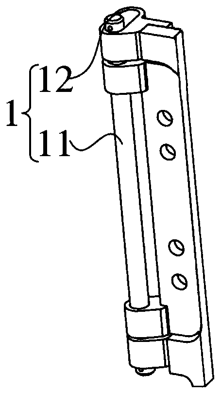
[0043] Specifically, as figure 1 As shown, the opening structure 1 includes a connected sliding member 12 and a rotating member 11, wherein the rotating member 11 can perform a translational movement relative to the sliding member 12, so that the two parts connected to the sliding member 12 and the rotating member 11 respectively, For example, the side plate 2 and the milling machine body 3 can be relatively translated and rotated.

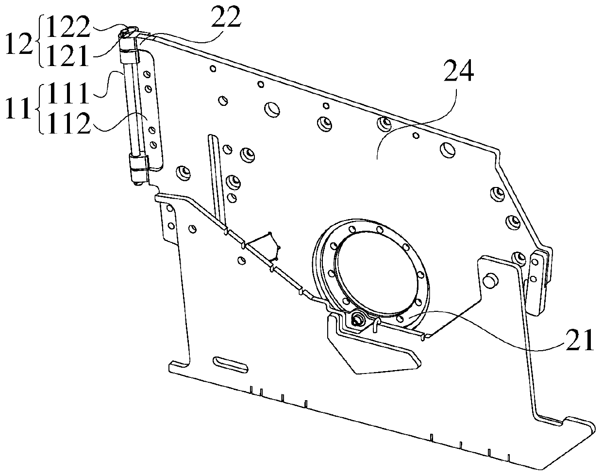
[0044] When the milling drum is arranged in the milling machine, the side plate 2 is provided with a support flange 21, and the support flange 21 abuts against the bearing support 41 of the milling drum, the rotating part 11 is used to make the side plate 2 relatively The milling drum rotates; a part of the rotating part 11 is arranged in the sliding part 12, so that the side plate 2 can translate along the axial direction of the bearing support 41, so as to be away from or close to the milling drum; the sliding part 12 is provided with a Connect...

Embodiment 2

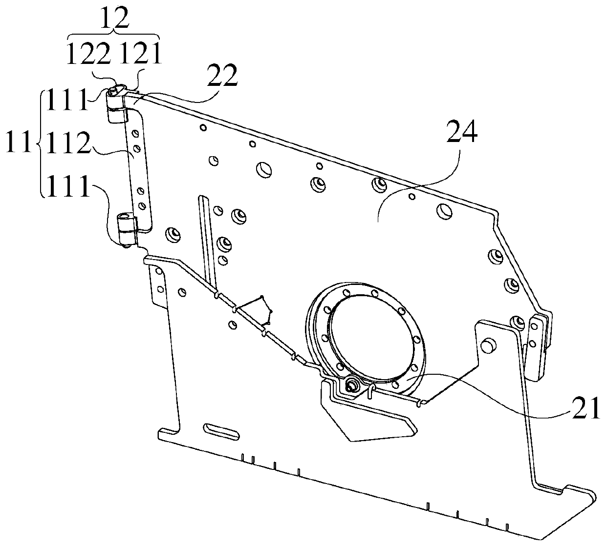
[0047] On the basis of Embodiment 1, further, the rotating member 11 includes a cylindrical part, and the sliding part 12 includes a long strip-shaped part suitable for the cylindrical part, and one axial end of the cylindrical part is loosely fitted with the long strip-shaped part , so that the cylindrical part can translate along the length direction of the elongated part, and enable the elongated part to make a circular motion around the axis of the cylindrical part.

[0048] Specifically, the rotating part 11 is provided with a position for the relative rotation of the sliding part 12, and by setting the part on the rotating part 11 for connecting with the sliding part 12 into a cylindrical shape, the rotation of the sliding part 12 can be more convenient, thereby facilitating The opening process of side plate 2 on the rotation mode. Similarly, the sliding part 12 is provided with a position for the relative sliding of the rotating part 11, and by setting the part on the s...

Embodiment 3

[0052] On the basis of embodiment one or embodiment two, further, as figure 1 As shown, the slider 12 includes a connecting portion 121, which is used to connect the side plate 2 or the milling machine body 3, and makes the extending direction of the elongated part perpendicular to the plane where the side plate 2 is located.

[0053] By setting the connecting part 121, the connecting part 121 for installing with the side plate 2 or the milling machine body 3 is provided for the sliding part 12 on the one hand, which facilitates the installation of the sliding part 12; The positional relationship between the guide groove and the side plate 2 helps to limit the opening route of the side plate 2 in the translational movement, making the opening more convenient and reducing the support flange 21 on the side plate 2 and the bearing support 41 of the milling machine possibility of interference.

[0054] Further, the connecting portion 121 is provided with a stepped surface, which ...


PUM


Abstract

The invention provides an opening structure of a side plate of a milling machine, the side plate and the milling machine. The opening structure comprises a rotating part used for making the side plateof the milling machine rotate relative to a milling drum, and a sliding part, wherein a part of the rotating part is arranged in the sliding part so that the side plate can horizontally move in the axis direction of a bearing support and get away from or close to the milling drum; the sliding part is of sufficient length, so that in the process that the side plate rotates relative to the millingdrum, a supporting flange and the bearing support are not in contact with each other all the time, and the possibility of interference is reduced. According to the opening structure, a combined structure capable of making the side plate rotate after translation is adopted, in the opening process of the side plate, the supporting flange and the bearing support are separated, interference during opening and closing is reduced, the structure is simple, and the operation is convenient. The structure of the milling machine does not need to be greatly improved, so that the cost is low. Compared withthe prior art, when the milling drum is replaced, people do not need to disassemble the whole side plate, and therefore time and labor are saved.

Description

technical field [0001] The invention relates to the technical field of road surface engineering equipment, in particular to an opening structure of a side plate of a milling machine, a side plate and a milling machine. Background technique [0002] With the continuous development of milling machines, there is a higher demand for the replacement efficiency of the milling drum. The current drum replacement method needs to disassemble the transmission door box, reducer and other components, and then remove the milling drum from the bearing support end. The milling drum is withdrawn. [0003] Since the milling drum needs to be pulled out from the bearing support end, the side plate needs to be designed as a structure that can be opened and closed. At present, the mainstream side plate opening and closing methods mainly include the following two types: [0004] The first method: single hinge + screw fixing, since opening the side plate directly will cause interference between th...

Claims


Application Information

Patent Timeline
Patent Type & Authority Applications(China)
IPC IPC(8): E01C23/088E01C23/12
CPCE01C23/088E01C23/12
Inventor 曾泽湘倪东升何财政
Owner SANY AUTOMOBILE MFG CO LTD
Features
  • R&D
  • Intellectual Property
  • Life Sciences
  • Materials
  • Tech Scout
  • Unparalleled Data Quality
  • Higher Quality Content
  • 60% Fewer Hallucinations
Learn More