Supercharge Your Innovation With Domain-Expert AI Agents!

Valve timing adjustment device

A technology of valve timing and adjustment devices, applied in the direction of valve devices, valve details, engine components, etc., which can solve the problem of stop pin stuck and so on

Pending Publication Date: 2020-12-18
DENSO CORP
View PDF1 Cites 0 Cited by
  • Summary
  • Abstract
  • Description
  • Claims
  • Application Information

AI Technical Summary

Problems solved by technology

However, when the lock is released, the stop pin may get caught by the upper groove, interfering with the release of the lock

Method used


Image

  • Valve timing adjustment device
  • Valve timing adjustment device
  • Valve timing adjustment device

Examples


Embodiment Construction

[0018] A. Example

[0019] A-1. Overall structure:

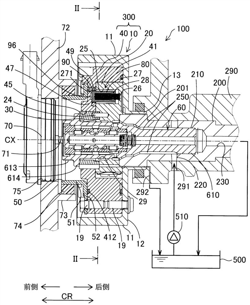
[0020] figure 1 The illustrated valve timing adjusting device 100 according to the embodiment of the present invention is installed at a driving force transmission path extending from a crankshaft (as a drive side shaft) to a camshaft (as a drive side shaft) at an internal combustion engine of a vehicle (not shown). moving side shaft) 200. Specifically, the valve timing adjusting device 100 is fixed to the end of the camshaft 200 . The valve timing adjusting device 100 adjusts a valve timing of a valve (not shown) that is opened and closed by a camshaft 200 . The rotation axis CX of the valve timing adjustment device 100 coincides with the rotation axis CX of the camshaft 200 . Among intake valves and exhaust valves (serving as valves), the valve timing adjusting device 100 of the present embodiment adjusts the valve timing of the intake valves.

[0021] The valve timing adjusting device 100 includes a pulley 10 , a hou...


PUM


Abstract

A valve timing adjustment device is provided with: a drive-side rotating body (300); a vane rotor (20); and a locking device (80) configured to lock rotation of the vane rotor (20) relative to the housing. The locking device (80) includes: a pin receiving portion (25) formed on the vane rotor; a recess (90) formed in the drive-side rotating body; a stop pin (27) received in the pin receiving portion and configured to reciprocate along the pin receiving portion and the recess; and a spring (28) configured to urge the stop pin. The recess has: a lower-side groove (91) configured to receive the stop pin; and an upper-side groove (92) joined to the lower-side groove in the circumferential direction and having a groove depth measured in the axial direction smaller than a groove depth measured in the axial direction of the lower-side groove. In a state in which the distal end surface of the stopper pin is in contact with the upper-side groove, an upper-side groove outer peripheral portion (98) does not face the distal end portion of the stopper pin at a surface extending in the axial direction, and the upper-side groove outer peripheral portion is a portion in which the outer periphery of the upper-side groove is not joined to the lower-side groove.

Description

technical field [0001] The invention relates to a valve timing adjustment device. Background technique [0002] Previously, a hydraulic valve timing adjustment device is known which is designed to adjust the valve timing of an intake valve or an exhaust valve of an internal combustion engine. One such valve timing adjusting device includes a lock device that locks the rotation of the vane rotor relative to a driving-side rotating body such as a housing. For example, in the locking device of the valve timing adjustment device described in WO / 2012 / 086085A1, when the oil pressure is insufficient to maintain the current rotational phase of the vane rotor, the stopper pin is inserted into the recess of the housing by the thrust of the spring , the locking device locks the rotation of the vane rotor relative to the housing, ie, the driving side rotating body. Furthermore, when the stop pin is removed from the recess in response to applying oil pressure to the stop pin, the lock ...

Claims


Application Information

Patent Timeline
Patent Type & Authority Applications(China)
IPC IPC(8): F01L1/344
CPCF01L1/344F01L1/024F01L1/3442F01L2001/34433F01L2001/3443F01L2001/34469F01L2001/34479F01L2001/0476F01L2250/02F01L2301/00
Inventor 竹中健一郎福山智之
Owner DENSO CORP
Features
  • R&D
  • Intellectual Property
  • Life Sciences
  • Materials
  • Tech Scout
  • Unparalleled Data Quality
  • Higher Quality Content
  • 60% Fewer Hallucinations
Learn More