Anchor cable sleeving and taking machine adopting shield method for tunnel crossing anchor cable construction

A technology of shield tunneling and anchor cable, which is applied in the installation of anchor rods, wellbore/well components, mining equipment, etc., can solve problems such as inconvenience in use, inconvenience in taking out the anchor cable, and low working efficiency of the anchor cable pulling machine.

Active Publication Date: 2019-12-31
CHINA CONSTR FOURTH ENG DIV
View PDF20 Cites 4 Cited by
  • Summary
  • Abstract
  • Description
  • Claims
  • Application Information

AI Technical Summary

Problems solved by technology

[0005] The purpose of the present invention is to provide a kind of anchor cable sheathing machine for shield tunnel crossing anchor cable construction, to solve the above-mentioned background technology. The anchor cable is taken out by grouting or filling to increase the friction between the anchor cable and the anchor cable casing. The work efficiency of the anchor cable lasso machine is low, and when the existing anchor cable lasso machine drills into the soil layer, the anchor cable lasso machine base needs to be stabilized, and the anchor cable lasso machine base is fixed, which is inconvenient to use The problem

Method used


Image

  • Anchor cable sleeving and taking machine adopting shield method for tunnel crossing anchor cable construction
  • Anchor cable sleeving and taking machine adopting shield method for tunnel crossing anchor cable construction
  • Anchor cable sleeving and taking machine adopting shield method for tunnel crossing anchor cable construction

Examples


Embodiment Construction

[0033] The following will clearly and completely describe the technical solutions in the embodiments of the present invention with reference to the accompanying drawings in the embodiments of the present invention. Obviously, the described embodiments are only some, not all, embodiments of the present invention. Based on the embodiments of the present invention, all other embodiments obtained by persons of ordinary skill in the art without making creative efforts belong to the protection scope of the present invention.

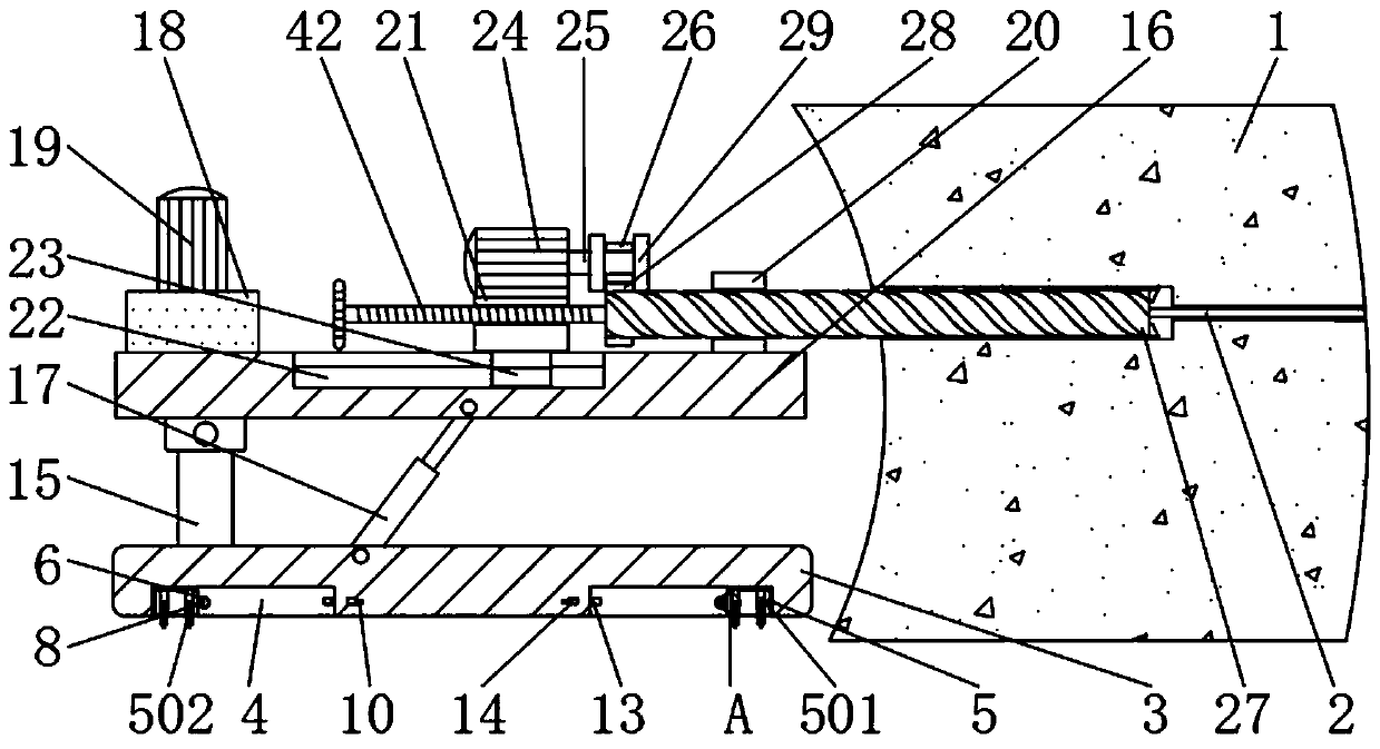
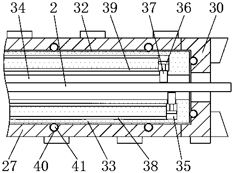
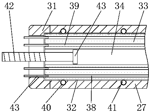
[0034] see Figure 1-6, the present invention provides a technical solution: An anchor cable sheathing machine for shield tunnel crossing anchor cable construction, including a soil layer 1, an anchor cable 2, a first base 3, a leg groove 4, a leg 5, a retaining Rod groove 6, first spring 7, stop rod 8, fixed rod groove 9, push button groove 10, fixed groove 11, second spring 12, fixed rod 13, push button 14, pillar 15, second base 16, hydraulic rod 17. Oil t...


PUM


Abstract

The invention relates to an anchor cable sleeving and taking machine adopting a shield method for tunnel crossing anchor cable construction. The anchor cable sleeving and taking machine comprises a soil layer, a first spring and balls. An anchor cable penetrates through the soil layer. A first base is arranged on one side of the soil layer. Supporting leg grooves are formed in the bottoms of the two sides of the longer side of the first base. Supporting legs are rotatably connected in the supporting leg grooves. Blocking rod grooves are formed in one side, close to the supporting legs, of thefirst base. The anchor cable sleeving and taking machine adopting the shield method for tunnel crossing anchor cable construction is provided with shearing frames. When an anchor cable groove completely sleeves the anchor cable at a tunnel construction site, a hydraulic motor injects hydraulic oil through a first oil groove, so that the hydraulic oil pushes a top plate to move outwards towards a top plate groove, and the top plate drives the shearing frames to move towards the anchor cable. When the shearing frames on the upper and lower sides move simultaneously towards the anchor cable, shearing force is formed between the shearing frames to shear the anchor cable, and meanwhile, the shearing frames prevent the anchor cable from moving out of the anchor cable groove, the anchor cable isdirectly taken out through an anchor cable sleeve, and grouting or injection filling is avoided.

Description

technical field [0001] The invention relates to the technical field of tunnel construction, in particular to an anchor cable lasso machine for shield tunnel crossing anchor cable construction. Background technique [0002] Shield method tunnel construction refers to the use of a shield machine to control the excavation surface and surrounding rock from collapse and instability while carrying out tunnel excavation and slag removal, assembling segments in the machine to form a lining, and implementing grouting behind the wall. In the method of constructing the tunnel without disturbing the surrounding rock, during the construction of the tunnel, when it is necessary to pass through the anchor cable area, in order to prevent the anchor cable from hindering the shield machine, the anchor cable needs to be taken out. [0003] At present, there are various types of anchor cable pulling machines, which are used to reduce labor intensity, improve work efficiency, and increase the us...

Claims


Application Information

Patent Timeline
IPC IPC(8): E21B23/00E21D21/00
CPCE21B23/00E21D21/00
Inventor 康卫刘双红李冬付小畅赵金鹏黄志良
Owner CHINA CONSTR FOURTH ENG DIV
Why Eureka
Try Eureka