Electromagnetic clutch

An electromagnetic clutch and electromagnetic coil technology, applied in the field of clutches, can solve the problems of transmission clearance and the clutch cannot be applied to transmission accuracy, and achieve the effects of ensuring accuracy, avoiding rigid impact, and eliminating friction.

Active Publication Date: 2020-09-15
采埃孚传动技术(嘉兴)有限公司
View PDF1 Cites 0 Cited by
  • Summary
  • Abstract
  • Description
  • Claims
  • Application Information

AI Technical Summary

Problems solved by technology

[0002] Publication No. CN103437878B provides a heavy-duty torsion shock-absorbing electromagnetic clutch assembly. This device divides the fan connection plate into the fan active connection plate and the fan passive connection plate and arranges the pressure spring for buffering and shock absorption between the two to form a In the cavity, so that when switching between high and low speeds, the pressure spring is only compressed by pressure and will not fall off from the cavity, which improves its stability in buffering and shock absorption, but after the clutch is turned on, the elastic component is always It is in a state of compression, so the elastic component will be compressed again when the torque changes, and there will be a transmission gap. This clutch cannot be applied to equipment with high transmission precision

Method used


Image

  • Electromagnetic clutch
  • Electromagnetic clutch
  • Electromagnetic clutch

Examples


Embodiment

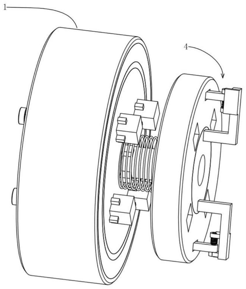
[0024] see Figure 1 to Figure 5 , the present invention provides a technical solution:

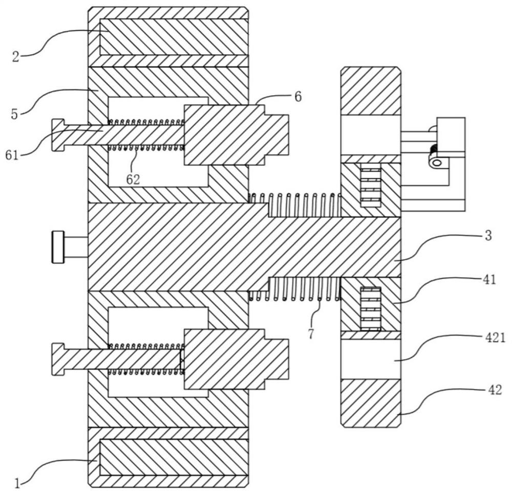
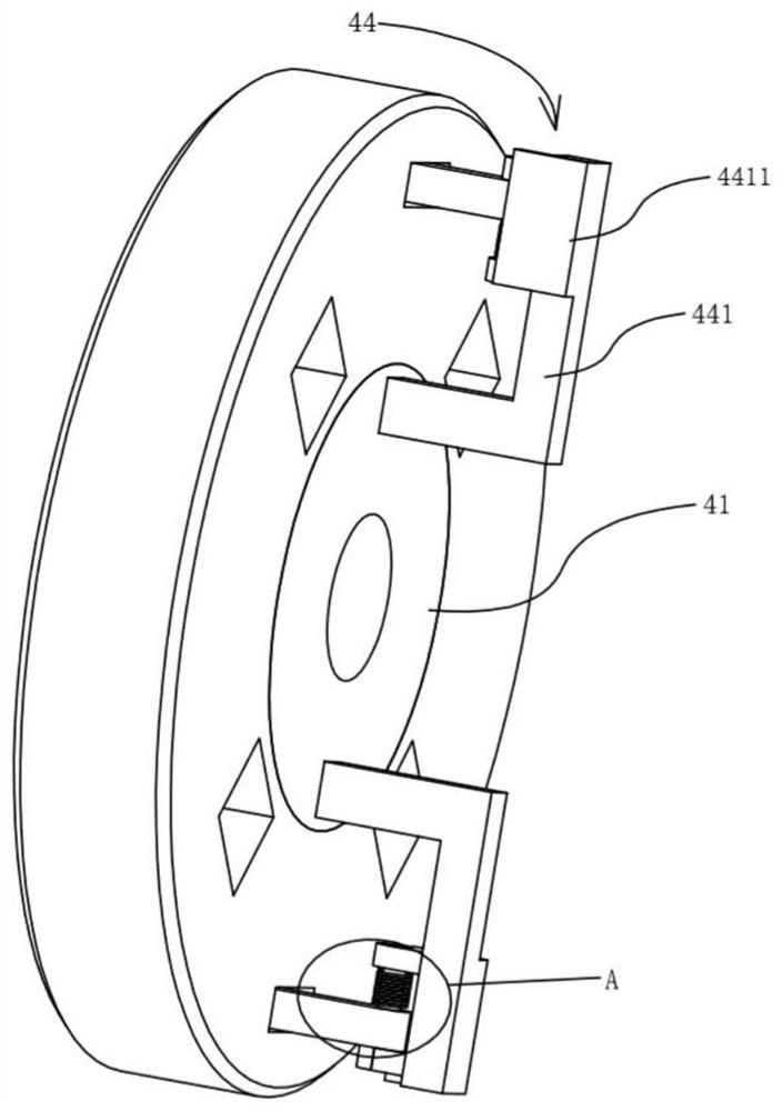
[0025] An electromagnetic clutch includes an electromagnetic coil housing 1, an electromagnetic coil 2, a drive shaft 3, a driven mechanism 4, a clutch disc 5, a plum blossom key 6 and a spring I7, wherein:

[0026] The electromagnetic coil 2 is arranged in the electromagnetic coil housing 1 to realize electromagnetic generation, and the clutch disc 5 is movably installed in the electromagnetic coil housing 1, wherein the clutch disc 5 can move in the circumferential direction and the axial direction of the electromagnetic coil housing 1. The drive shaft 3 is provided with key teeth and the clutch disc 5 is provided with key grooves matching the key teeth. With the axial movement of the drive shaft 3, the plum blossom key 6 is movably installed on the clutch disc 5 and extends out of the end face of the clutch disc 5. The end of the plum blossom key 6 is provided with a mounting rod 61, ...


PUM


Abstract

The invention provides an electromagnetic clutch. The electromagnetic clutch comprises an electromagnetic coil shell, electromagnetic coils, a drive shaft, a driven mechanism, a clutch disc, a plum blossom key and a spring I, wherein the plum blossom key is movably arranged on the clutch disc and extends out of the end face of the clutch disc, a rotary disc in the driven mechanism sleeves the endof the drive shaft through a bearing, the spring I is arranged between the rotary disc and the clutch disc, a circular ring is rotationally arranged in the rotary disc, springs are arranged in the rotary disc, the inner and outer rings of the springs are fixedly connected with the rotary disc and the circular ring respectively, and at least two locking mechanisms are arranged on the rotary disc and are used for limiting the position of the circular ring. The plum blossom key movably arranged on the clutch disc is in butt joint with a butt joint groove to realize clutch, a spring is arranged between the plum blossom key and the clutch disc, so that friction between the plum blossom key and the circular ring when the plum blossom key is not in butt joint with the butt joint groove can be effectively eliminated, the flexible connection between the rotary disc and the circular ring is facilitated, and the rigid impact caused by the large torque transmission to each part can be avoided.

Description

technical field [0001] The invention relates to the technical field of clutches, in particular to an electromagnetic clutch. Background technique [0002] Publication No. CN103437878B provides a heavy-duty torsion shock-absorbing electromagnetic clutch assembly. This device divides the fan connection plate into the fan active connection plate and the fan passive connection plate and arranges the pressure spring for buffering and shock absorption between the two to form a In the cavity, so that when switching between high and low speeds, the pressure spring is only compressed by pressure and will not fall off from the cavity, which improves its stability in buffering and shock absorption, but after the clutch is turned on, the elastic component is always It is in a state of compression, so when the torque changes, the elastic component will be compressed again, and there will be a transmission gap. This clutch cannot be applied to equipment with high transmission precision. ...

Claims


Application Information

Patent Timeline
Patent Type & Authority Patents(China)
IPC IPC(8): F16D27/02
CPCF16D27/02
Inventor 金怀璧
Owner 采埃孚传动技术(嘉兴)有限公司
Why Eureka
Try Eureka