An assembly method of a wireless charging receiving coil module

A receiving coil and wireless charging technology, which is applied in the direction of transformer/inductor coil/winding/connection, coil manufacturing, circuit device, etc., can solve the problems of superposition of connecting wire and coil body thickness, expensive equipment cost, and increased local thickness. Achieve the effects of reducing heat generation of electronic equipment, reducing charging efficiency, and reducing assembly thickness

Active Publication Date: 2021-09-03
苏州蓝沛无线通信科技有限公司
View PDF9 Cites 0 Cited by
  • Summary
  • Abstract
  • Description
  • Claims
  • Application Information

AI Technical Summary

Problems solved by technology

At present, the total thickness of the wireless charging receiver module depends on the thickness of the assembly assembly of magnetic materials, coils and connecting wires. It is usually assembled by connecting the lead wires at the end of the inner ring of the coil to the lead wires at the end of the outer ring of the coil. The thickness of the connecting wire and the coil body will be superimposed, resulting in an increase in local thickness. In addition, the excessively thick connecting wire needs to open a window or slot on the magnetic isolation sheet, which will cause magnetic flux leakage, resulting in a decrease in charging efficiency and heating of electronic equipment. disadvantages
There are many manufacturing processes in this way, and it also makes the production process more complicated, and the equipment cost in the early stage is relatively expensive.

Method used


Image

  • An assembly method of a wireless charging receiving coil module
  • An assembly method of a wireless charging receiving coil module
  • An assembly method of a wireless charging receiving coil module

Examples


Embodiment Construction

[0085] The present invention will be described in detail below in conjunction with the accompanying drawings and specific embodiments. The present invention is not limited to this embodiment, and other embodiments may also belong to the scope of the present invention as long as they conform to the gist of the present invention.

[0086] In a preferred embodiment of the present invention, based on the above-mentioned problems in the prior art, a method for assembling a wireless charging receiving coil module is provided. The wireless charging receiving coil module includes a receiving coil and a multi-layer magnetic material, and the receiving coil includes an inner outgoing line located at the inner layer of the receiving coil and an outer outgoing line located at the outer layer of the receiving coil;

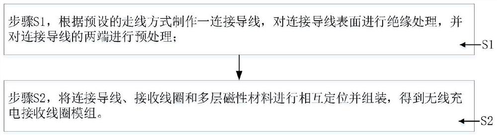
[0087] Such as figure 1 As shown, the assembly method of the wireless charging receiving coil module specifically includes:

[0088] Step S1, making a connecting wire accord...


PUM


Abstract

The invention provides a method for assembling a wireless charging receiving coil module, which relates to the technical field of wireless charging. The wireless charging receiving coil module includes a receiving coil and a multi-layer magnetic material, and the receiving coil includes a receiving coil located in the inner layer of the receiving coil. An inner outgoing line and an outer outgoing line located on the outer layer of the receiving coil; the assembly method specifically includes: making a connecting wire according to a preset wiring method, insulating the surface of the connecting wire, and pretreating both ends of the connecting wire; The connecting wire, the receiving coil and the multi-layer magnetic material are mutually positioned and assembled to obtain a wireless charging receiving coil module. Effectively reduce the thickness of the assembly of the wireless charging receiving coil module; only need to make local slots on the multi-layer magnetic material, effectively reducing the possibility of problems such as reduced charging efficiency and heating of electronic equipment caused by magnetic flux leakage of the multi-layer magnetic material Sex; the assembly process is effectively simplified, and the manufacturing cost is greatly reduced.

Description

technical field [0001] The invention relates to the technical field of wireless charging, in particular to a method for assembling a wireless charging receiving coil module. Background technique [0002] Wireless charging coils, also known as inductive charging coils or non-contact charging coils, are a new type of charging technology derived from wireless power transmission technology, which can be used for short-range non-contact wireless charging devices that transmit energy using the principle of near-field induction conduction Wirelessly charge mobile communication devices, personal computer devices, small smart electronic devices, smart wearable products, etc. In the field of consumer electronics, products tend to be thinner and smaller, and the space left for placing wireless charging coils is getting smaller and smaller. How to reduce the thickness of wireless charging coil modules as much as possible has become an urgent problem to be solved. [0003] The wireless ...

Claims


Application Information

Patent Timeline
Patent Type & Authority Patents(China)
IPC IPC(8): H01F41/00H01F41/10H01F41/12H01F38/14H01F27/29H01F27/28H01F27/24H01F27/34H02J50/10
CPCH01F27/24H01F27/28H01F27/29H01F27/346H01F38/14H01F41/00H01F41/10H01F41/125H02J50/10
Inventor 戴飞吴长和林涛王劲
Owner 苏州蓝沛无线通信科技有限公司
Why Eureka
Try Eureka