
Cooling components and electronic equipment

A technology for heat-dissipating components and electronic equipment, which is applied in the structural parts of electrical equipment, electrical components, cooling/ventilation/heating renovation, etc. Conducive to heat dissipation, reducing assembly thickness, and reducing the effect of contact area

Active Publication Date: 2021-03-12
GUANGDONG OPPO MOBILE TELECOMM CORP LTD
View PDF10 Cites 0 Cited by
  • Summary
  • Abstract
  • Description
  • Claims
  • Application Information

AI Technical Summary

Problems solved by technology

Heat pipes are widely used in the heat dissipation of electronic equipment. Due to the structural limitations of heat pipes, the heat dissipation efficiency of electronic equipment is not high, and it is not conducive to thinning the thickness of electronic equipment.

Method used


Image

  • Cooling components and electronic equipment
  • Cooling components and electronic equipment
  • Cooling components and electronic equipment

Examples


Embodiment

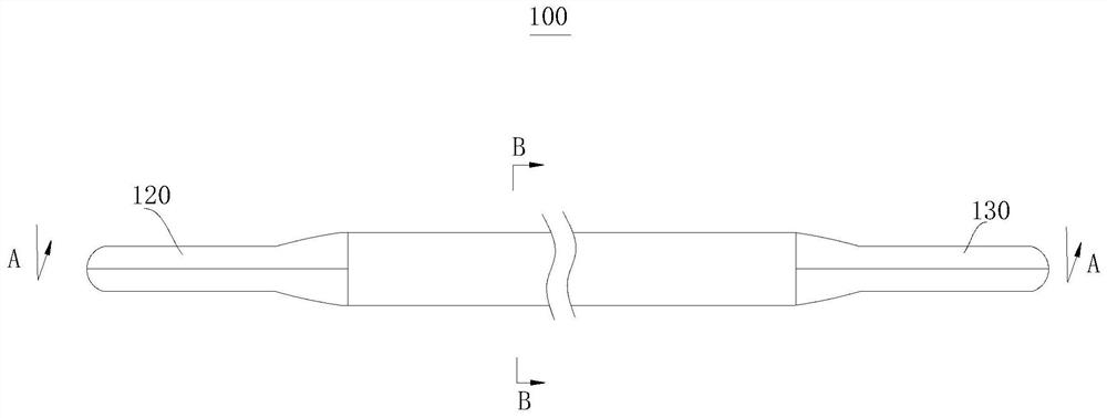
[0021] Please also refer to figure 1 and figure 2 , this embodiment provides a heat dissipation assembly 100, which can be applied to such as Figure 5 or Figure 7 As shown in the electronic device 200, the heat dissipation assembly 100 includes a tube body 110, a first flat connection part 120, a second flat connection part 130, a liquid-absorbing core 130 and a working medium 140, and the first flat connection part 120 and the second flat connection part The part 130 is connected to the tube body 110 , the liquid-absorbing core 130 is arranged in the tube body 110 , and the working medium 140 is filled in the tube body 110 .

[0022] see figure 2 , the tubular body 110 has an opposite first end 114 and a second end 115, the first flat connecting portion 120 is connected to the first end 114, the second flat connecting portion 130 is connected to the second end 115, the tubular body 110 1. The first flat connection part 120 and the second flat connection part 130 enclo...


PUM


Abstract

An embodiment of the present application provides a heat dissipation assembly, including a pipe body, a first flat connection part, a second flat connection part, a liquid-absorbing core, and a working medium. The pipe body has a first end and a second end opposite to each other. A flat connecting part is connected to the first end of the tube body, a second flat connecting part is connected to the second end, the tube body, the first flat connecting part and the second flat connecting part enclose a medium cavity, and the liquid-absorbing core is arranged on the In the medium cavity, the working medium is encapsulated in the medium cavity. By providing the first flat connection part and the second flat connection part, the frame of the electronic device can be directly connected through the first flat connection part and the second flat connection part, thereby reducing the contact between the heat dissipation component and the housing of the electronic device The area reduces the thermal resistance and facilitates heat dissipation. In addition, the first flat connection part and the second flat connection part are connected to the middle frame of the electronic device, which is beneficial to the light and thin design of the product. In addition, an electronic device including the above heat dissipation component is also provided.

Description

technical field [0001] The present application relates to the field of electronic equipment, in particular to a heat dissipation component and electronic equipment. Background technique [0002] With the continuous development of electronic equipment, the heat generated due to the high integration and high performance of the internal components of the electronic equipment has been increasing in recent years. In addition, due to the increase in heat generation density due to the advancement of product miniaturization, countermeasures against heat dissipation are becoming more and more important. Heat pipes are widely used in the heat dissipation of electronic devices. Due to the structural limitations of heat pipes, the heat dissipation efficiency of electronic devices is not high, and it is not conducive to reducing the thickness of electronic devices. Contents of the invention [0003] In view of the above problems, the purpose of the present application is to provide a ...

Claims


Application Information

Patent Timeline
Patent Type & Authority Patents(China)
IPC IPC(8): H05K7/20
CPCH05K7/20336
Inventor 贾玉虎
Owner GUANGDONG OPPO MOBILE TELECOMM CORP LTD
Learn More