Power system suitable for small vertical take-off and landing fixed-wing aircraft

A technology of vertical take-off and landing and power system, applied in the field of power system, can solve the problems of complex structure, single function, heavy weight, etc., and achieve the effect of simplifying the complexity of the structure, reducing the weight of the structure, and improving the efficiency

Active Publication Date: 2020-01-03
NANJING UNIV OF AERONAUTICS & ASTRONAUTICS
View PDF5 Cites 6 Cited by
  • Summary
  • Abstract
  • Description
  • Claims
  • Application Information

AI Technical Summary

Problems solved by technology

[0003] The power system is a difficult point in the development of vertical take-off and landing fixed-wing aircraft, and it plays a vital role in realizing the function of vertical take-off and landing. Among various power systems, the combined power system relies on the nozzle that can be deflected downward and through the engine The shaft-driven lift fan can greatly increase the lift provided and has superior performance, but this combined power system has a complex structure and heavy weight, and the two power subsystems are controlled by a single motor, which requires a transmission clutch system
[0004] In the combined power system, the vector nozzle technology is generally used to achieve vertical take-off and landing. The three-bearing vector nozzle is a large-rotation-angle thrust vector nozzle used in vertical take-off and landing fixed-wing aircraft. The three-section nozzle rotates with each other To achieve the deflection of the overall nozzle surface, the use of vector nozzles can reduce the requirements for take-off and landing sites and the difficulty of deployment, and greatly improve the survivability of vertical take-off and landing fixed-wing aircraft. Large, unable to meet various flight conditions

Method used


Image

  • Power system suitable for small vertical take-off and landing fixed-wing aircraft
  • Power system suitable for small vertical take-off and landing fixed-wing aircraft
  • Power system suitable for small vertical take-off and landing fixed-wing aircraft

Examples


Embodiment Construction

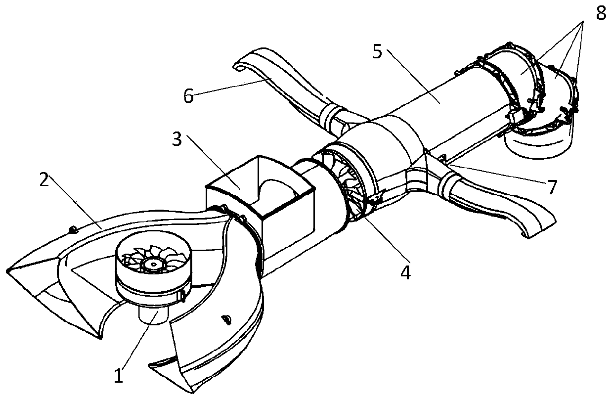
[0041] refer to figure 1 Shown, the power system that the present invention is applicable to small vertical take-off and landing fixed-wing aircraft comprises two independent power subsystems, is respectively lift fan and auxiliary motor power subsystem 1 and main ducted fan and main motor power subsystem, and A biasing system.

[0042] The lift fan and the auxiliary motor power subsystem 1 are installed in the front fuselage section; the main ducted fan and the main motor power subsystem include two main air inlets 2 symmetrically arranged on both sides of the front of the fuselage, and one on the fuselage side and connected between the main air inlet 2 and the main duct fan 4, the guide cylinder 5 behind the main duct fan 4, and the vector nozzle connected to the rear of the guide cylinder 5 Pipe 8; the deflection system includes two rolling nozzles 6 installed on both sides of the guide cylinder 5 wall, and the rolling control adjustment mechanism 7 in the rolling nozzle 6...


PUM


Abstract

The invention relates to a power system suitable for a small vertical take-off and landing fixed-wing aircraft. The system comprises two independent power subsystems and a drifting system, wherein thepower subsystems comprise a lift fan and auxiliary motor power subsystem, a main ducted fan and main motor power subsystem, the lift fan and auxiliary motor power subsystem is used for generating downward airflow, so that first vertical lifting force is generated located at the front part of a fuselage; and the main ducted fan and main motor power subsystem is used for downwards deflecting gas jetted backwards through a main ducted fan via a vector spray pipe to generate second vertical lifting force located at the tail part of the fuselage, and the drifting system directs compressed air generated by the main ducted fan to wings of the two sides through two rolling spray pipes, and then the air is jetted downwards through nozzles on wingtips so as to generate third vertical lifting forceat the wings on the two sides. Airflow adjusting mechanisms are arranged in the two rolling spray pipes, and are used for adjusting the air injection amount of the two rolling spray pipes, so that a rolling moment is generated, the downward jetted air is deflected clockwise or counterclockwise by deflecting a first spray pipe unit, so that a yaw moment is generated.

Description

technical field [0001] The invention relates to a power system suitable for a small vertical take-off and landing fixed-wing aircraft, which belongs to the technical field of aviation aircraft design. Background technique [0002] The vertical take-off and landing fixed-wing aircraft can take off in a short distance, then convert to fixed-wing mode flight, and finally land vertically. It is a research hotspot in various countries in recent years. [0003] The power system is a difficult point in the development of vertical take-off and landing fixed-wing aircraft, and it plays a vital role in realizing the function of vertical take-off and landing. Among various power systems, the combined power system relies on the nozzle that can be deflected downward and through the engine The shaft-driven lift fan can greatly increase the lift provided and has superior performance. However, this combined power system has a complex structure and a large weight. The two power subsystems a...

Claims


Application Information

Patent Timeline
Patent Type & Authority Applications(China)
IPC IPC(8): B64C29/00
CPCB64C29/0083
Inventor 王子安龚正刘朋辉王欣艺吕慧涛张同任
Owner NANJING UNIV OF AERONAUTICS & ASTRONAUTICS
Why Eureka
Try Eureka