
Design method of shock wave rod device installed on head of supersonic aircraft

A design method and technology for aircraft, which are applied to ground installations, aircraft parts, transportation and packaging, etc., can solve the problems that affect drag reduction and heat protection effects, and the flow field structure at the front of the aircraft has a greater impact, so as to improve force/heat environment, improve design ability, and realize the effect of refactoring

Inactive Publication Date: 2020-01-03
BEIJING SPACE TECH RES & TEST CENT
View PDF5 Cites 16 Cited by
  • Summary
  • Abstract
  • Description
  • Claims
  • Application Information

AI Technical Summary

Problems solved by technology

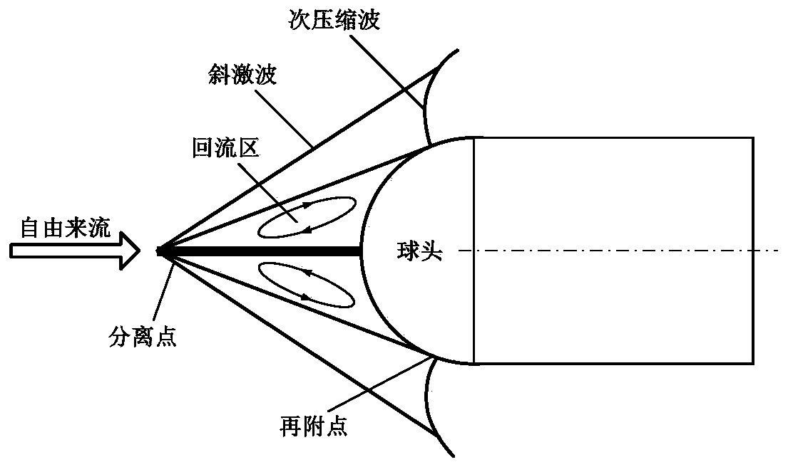
However, the position, geometric configuration, jet angle, jet pressure ratio and other parameters of the jet hole have a great influence on the flow field structure in the front of the aircraft, thus affecting the overall drag reduction and heat protection effect.

Method used


Image

  • Design method of shock wave rod device installed on head of supersonic aircraft
  • Design method of shock wave rod device installed on head of supersonic aircraft
  • Design method of shock wave rod device installed on head of supersonic aircraft

Examples


Embodiment Construction

[0026] In order to more clearly describe the embodiments of the present invention or the technical solutions in the prior art, the following will briefly introduce the drawings that are used in the embodiments. Apparently, the drawings in the following description are only some embodiments of the present invention, and those skilled in the art can also obtain other drawings according to these drawings without creative efforts.

[0027] When describing the embodiments of the present invention, the terms "vertical", "transverse", "upper", "lower", "front", "rear", "left", "right", "vertical", " The orientation or positional relationship expressed by "horizontal", "top", "bottom", "inner" and "outer" is based on the orientation or positional relationship shown in the relevant drawings, which are only for the convenience of describing the present invention and simplifying the description, and It is not to indicate or imply that the device or element referred to must have a particu...


PUM


Abstract

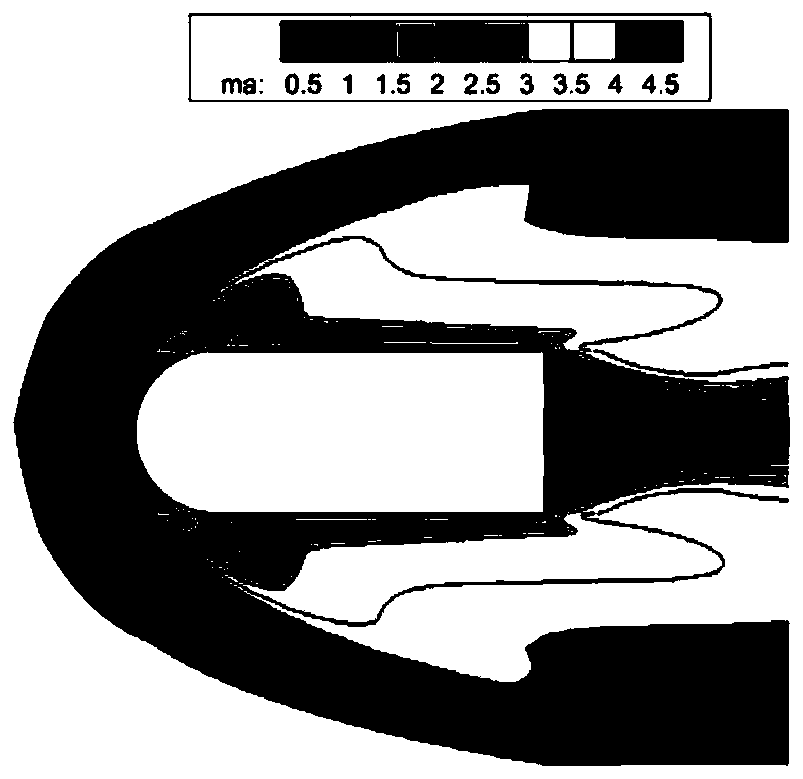
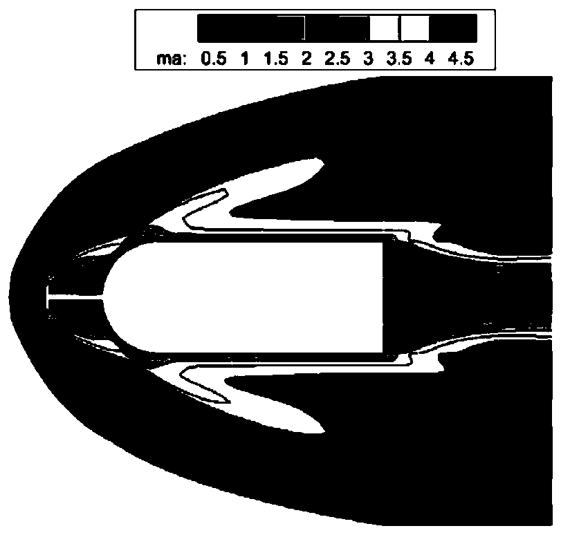
The invention relates to a design method of a shock wave rod device installed on the head of a supersonic aircraft. The design method comprises the following steps that a, the flow field condition ofan initial configuration of an aircraft without a drag reduction device under a supersonic flight working condition is analyzed to obtain flow field information; b, according to the flow field information, the initial configuration and size parameters of the shock wave rod device are initially planned; c, based on the initial configuration of the shock wave rod device, a jet flow structure is designed on the shock wave rod device; and d, whether the initial configuration of the shock wave rod device with the jet flow structure meets the aerodynamic characteristic requirement of the supersonicaircraft or not is analyzed, if not, the step b is returned, and if yes, and the geometric configuration of the shock wave rod device with the jet flow structure is determined. According to the designmethod of the shock wave rod device, by adding the shock wave rod device with a jet hole, the relevant parameters are optimized and selected, so that the reconstruction of the flow field of the headof the aircraft is realized, the force / thermal environment near the head is improved, the design capability of the aircraft is improved.

Description

technical field [0001] The invention relates to the field of supersonic vehicle design and optimization, in particular to a design method of a shock rod device installed on the head of a supersonic vehicle. Background technique [0002] With the increasing demand for space offensive and defensive systems and information operations such as long-range rapid and efficient strike platforms and high-speed reusable platforms around the world, the development of near-space hypersonic vehicle technology has become increasingly important. The United States, Russia, and European countries have invested a lot of money in the research of technology in this field, which mainly includes the overall design technology of hypersonic aircraft, aerodynamic / thermal integration technology, high-temperature long-term thermal protection technology, high-precision GNC technology and engine technology. technology etc. Among the above technologies, drag reduction and heat protection of hypersonic ve...

Claims


Application Information

Patent Timeline
Patent Type & Authority Applications(China)
IPC IPC(8): B64F5/00
CPCB64F5/00
Inventor 赵飞左光石泳段润泽万千刘丽玲徐艺哲杜若凡吕凡熹
Owner BEIJING SPACE TECH RES & TEST CENT
Learn More