Combined multi-channel end face sealing rotary compensator

A technology of rotary compensator and end face sealing, which is applied to expansion compensation devices for pipelines, pipes/pipe joints/pipes, adjustable connections, etc. Filling loss and other problems, to achieve the effect of long service life, high bearing strength, and enhanced sealing

Pending Publication Date: 2020-01-07
JIANGSU YONGLI PIPELINE CO LTD
View PDF0 Cites 3 Cited by
  • Summary
  • Abstract
  • Description
  • Claims
  • Application Information

AI Technical Summary

Problems solved by technology

For pipelines conveying high-temperature and high-pressure media, due to the inevitable assembly gap of the pipeline compensator and the low strength of traditional sealing packing, coupled with the action of high-temperature and high-pressure media, the deflection and displacement of the packing material in the compensator medium loss
On the other hand, the assembly gap of the traditional pipeline compensator is usually designed to be close to the outer surface of the inner core pipe. During the working process, the medium will penetrate along the assembly gap to the root of the sealing packing, and accelerate the loss and blowing of the sealing packing
Such a design is more likely to cause the failure of the "labyrinth effect" that prevents the leakage of the medium, resulting in a large loss of the sealing packing of the compensator, which is easy to leak and shortens the service life.

Method used


Image

  • Combined multi-channel end face sealing rotary compensator

Examples


Embodiment Construction

[0021] Below in conjunction with accompanying drawing and specific embodiment the present invention will be further described:

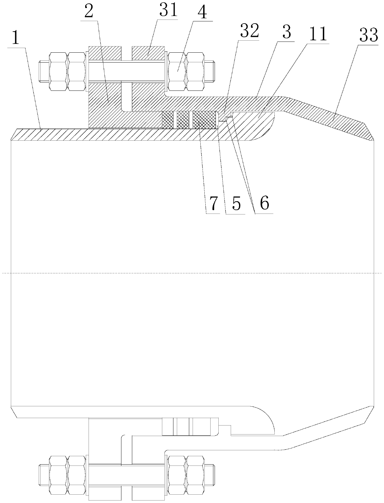
[0022] Such as figure 1 As shown, the combined multi-channel end face seal rotary compensator includes a rotary seat 3, a rotary core tube 1 and a packing gland 2. The inner surface of the inner surface of the rotating core tube 1 and the outer surface of the rotating core tube 1 form a packing sealing cavity, and a sealing packing is arranged in the sealing cavity. The inner wall of the rotating seat 3 is provided with an inner convex ring 32. The stepped outer boss 11 matched with the convex ring 32, the assembly gap formed between the outer boss 11 and the inner convex ring 32 is located in the middle of the bottom of the sealed cavity; the outer boss 11 of the rotating core tube 1 is at least There are two steps, and an end face sealing ring 6 is embedded between the side of the steps and the opposite surface of the inner convex ring 32 .

[00...


PUM


Abstract

The invention relates to a combined multi-channel end face sealing rotary compensator. The combined multi-channel end face sealing rotary compensator comprises a rotary seat, a rotary core tube and apacking gland, wherein a sealing filler is arranged in a sealing cavity; an inner convex ring is arranged on the inner wall of the rotary seat; a stepped outer boss is arranged at the right end of therotary core pipe; and an assembly gap between the outer boss and the inner convex ring is positioned at the middle position of the bottom of the sealing cavity; the outer boss of the rotary core tubeis provided with at least two steps, and an end face sealing ring is embedded between the side surface of the step and the inner convex ring. The sealing filler comprises a pressure-change metal ringand a nonmetallic flexible filler, wherein the pressure-change metal ring generates radial expansion and deformation under the action of an external force, and the inner and outer side edges of the pressure-change metal ring are closely matched with the side wall of the sealing cavity. According to the combined multi-channel end face sealing rotary compensator, a multistage end face sealing ringis arranged between the outer boss of the rotary core tube and the inner boss of the outer sleeve, and the sealing ring forms a positive correlation self-sealing effect along with the change of the pressure of the pipeline medium, so that the sealing effect is enhanced. The combined multi-channel end face sealing rotary compensator has the advantages of strong high temperature resistance, high pressure resistance, good sealing effect, long service life and convenient installation.

Description

technical field [0001] The invention relates to the technical field of pipeline compensators, in particular to a combined multi-channel end face seal rotary compensator. Background technique [0002] Pipeline compensators generally require sealing packing to keep the pipeline sealed and prevent medium leakage. The existing sleeve compensator compensates the displacement of the pipeline through the expansion and contraction of the sliding core tube. The seal between the sliding core tube and the filler cannot be kept in a good state for a long time, and leakage is likely to occur after long-term use. A sealing packing cavity is provided between the inner and outer tubes of the rotary compensator, and the sealing packing is put into the sealing cavity, and the sealing packing is pressed by the packing gland to realize the sealing. The rotating parts of the rotary compensator have a relatively large fit gap, and are affected by the thrust of the pipeline. The stability of the ...

Claims


Application Information

Patent Timeline
Patent Type & Authority Applications(China)
IPC IPC(8): F16L51/00F16L27/08
CPCF16L27/08F16L51/00
Inventor 潘文浩
Owner JIANGSU YONGLI PIPELINE CO LTD
Why Eureka
Try Eureka