A bullet structure for improving the ballistic stability of projectile penetrating concrete target plate
A concrete and stability technology, applied in the direction of warheads, ammunition, offensive equipment, etc., can solve problems such as easy deflection of ballistics, and achieve the effect of improving the performance of anti-bounce bullets, improving ballistic stability, and balancing destructive moments
- Summary
- Abstract
- Description
- Claims
- Application Information
AI Technical Summary
Problems solved by technology
Method used
Image
Examples
Embodiment 1
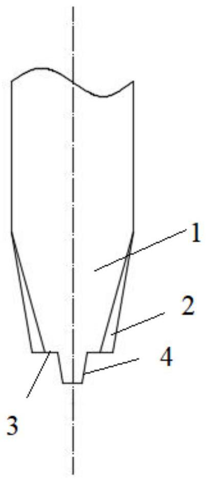
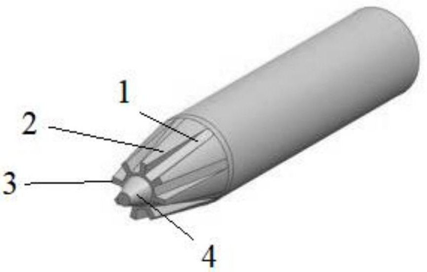
[0044] This embodiment provides a bullet structure for improving the ballistic stability of the projectile penetrating the concrete target plate, such as Figure 1 to Figure 4 As shown, including the warhead body, the front end of the warhead body is provided with a first round table 1, and the diameter of the upper bottom surface of the first round table 1 is smaller than the diameter of the bottom surface of the first round table 1; a rib 2; the end of the rib 2 away from the first circular platform 1 is the front end of the rib 2, and the other end of the rib 2 is the rear end of the rib 2; the height of the front end of the rib 2 is greater than the height of the rear end of the rib 2; the rear of the rib 2 The diameter at the end is equal to the diameter of the bottom surface of the first circular platform 1; the rib plate 2 is used to improve the ballistic stability of the projectile penetrating the concrete target plate.
[0045] Specifically, the projectile structure i...
Embodiment 2
[0071] This embodiment is used to calculate the trajectory and velocity of the ribbed plate 2 warhead penetrating concrete. Using a ribbed 2 warhead projectile with a mass of 4.2kg, Table 1 shows the specific values of the ribbed 2 warhead size for calculation. The target plate thickness is 0.4m, the concrete compressive strength is 34.26Mpa, and the initial velocity of the projectile is 600m / s.
[0072] Table 1 Shape parameter list of type 2 warhead with ribs
[0073]
[0074] In Table 1, d is the diameter of the bottom surface of the truncated cone, mm; d 1 is the diameter of the upper bottom surface of the second round table 4, mm; d 2 is the diameter of the bottom surface of the second circular platform 4, mm, d 3 is the diameter mm of the upper bottom surface of the first circular platform; d 3 is the 3 diameter mm of the bottom surface of the first circular platform; d 4 is the diameter of the bottom surface of the rib plate 2 mm; w min is the minimum width of...
Embodiment 3
[0079] In this embodiment, the 4.2kg ribbed Type 2 head projectile with an initial velocity of 500m / s and a 25° impact angle obliquely penetrates into a 0.4m thick concrete target plate, and the diameter d1 of the upper bottom surface of the flange is changed, and the diameter is respectively taken as 10.5 mm, 14.5mm and 18.5mm.
[0080] After the penetration is over, draw the deflection angle time history curve as attached Figure 7 As shown, as the diameter of the upper bottom surface of the flange increases, the deflection angle of the ribbed type 2 projectile body decreases and the velocity also decreases faster, which is due to the increase of the axial force, the increase of the moment arm, and the resistance deflection caused by the axial force The moment of the projectile increases, so the deflection angle of the projectile body decreases. When designing the projectile body, the diameter of the upper bottom surface of the flange can be appropriately increased to increa...
PUM
 Abstract
Description
Claims
Application Information
 - R&D
- Intellectual Property
- Life Sciences
- Materials
- Tech Scout
- Unparalleled Data Quality
- Higher Quality Content
- 60% Fewer Hallucinations
Browse by: Latest US Patents, China's latest patents, Technical Efficacy Thesaurus, Application Domain, Technology Topic, Popular Technical Reports.
© 2025 PatSnap. All rights reserved.Legal|Privacy policy|Modern Slavery Act Transparency Statement|Sitemap|About US| Contact US: help@patsnap.com


