
Locking clamp and collimation inspection device

A technology of locking clips and locking segments, which is applied to aiming devices, workpiece clamping devices, manufacturing tools, etc., can solve the problems of complexity, unfavorable production efficiency, and long time-consuming scopes, and achieve the effect of improving accuracy.

Inactive Publication Date: 2020-01-10
珠海天羿精密仪器有限公司
View PDF0 Cites 2 Cited by
  • Summary
  • Abstract
  • Description
  • Claims
  • Application Information

AI Technical Summary

Problems solved by technology

[0003] In order to fix the scope accurately, generally speaking, the process of locking and unlocking the scope will be complicated, and the process of locking and unlocking the scope will take a long time, which is not conducive to improving production efficiency.

Method used


Image

  • Locking clamp and collimation inspection device
  • Locking clamp and collimation inspection device
  • Locking clamp and collimation inspection device

Examples


Embodiment Construction

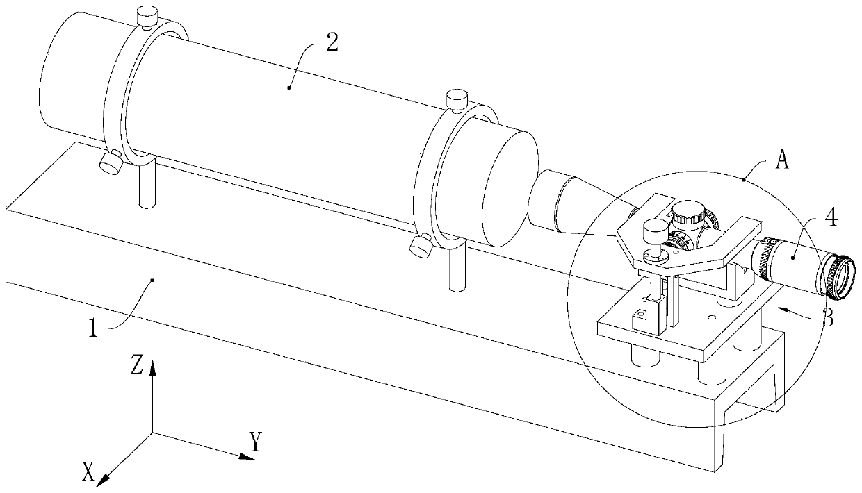
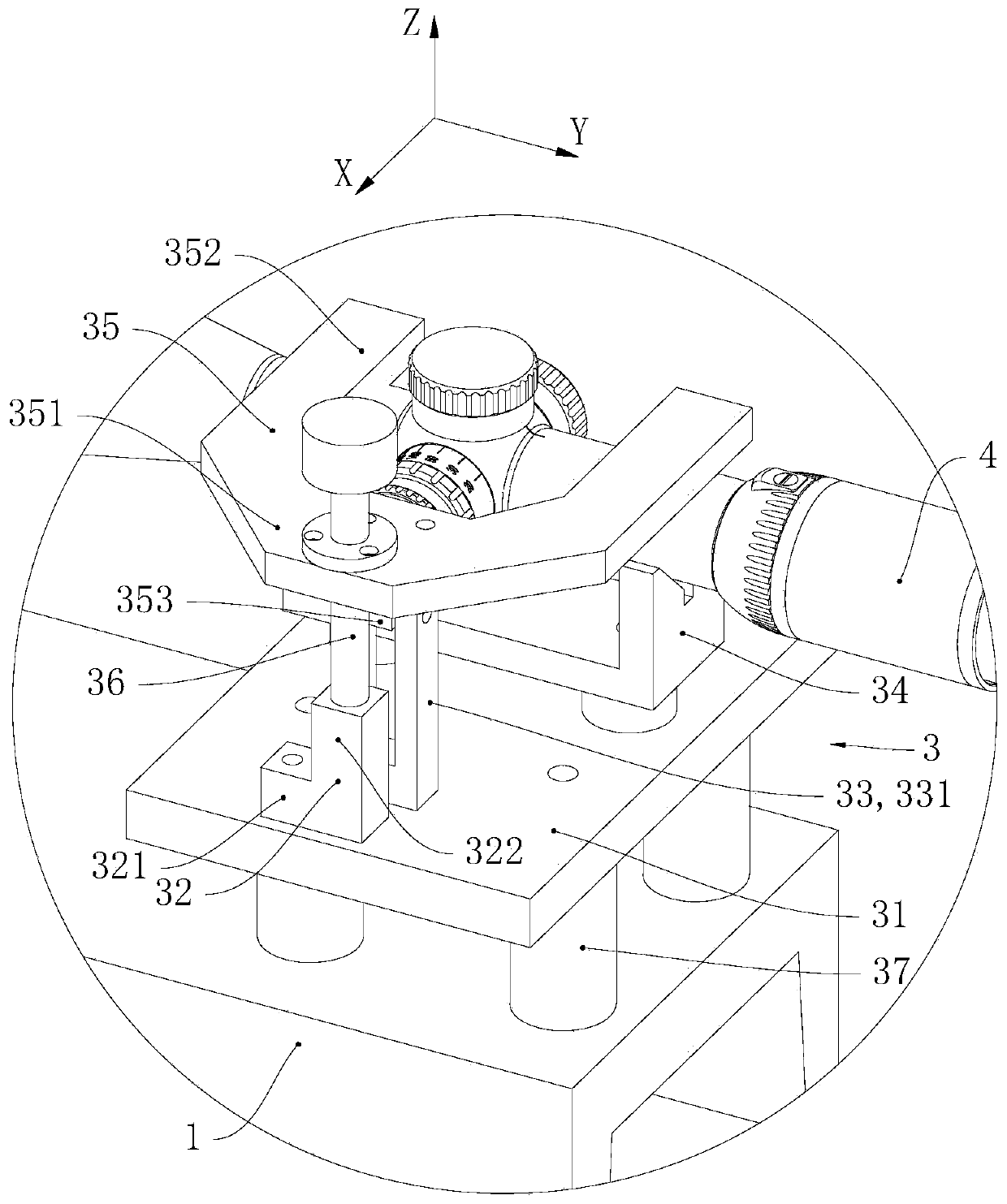
[0026] This example refers to figure 1 The spatial Cartesian coordinate system shown is described.

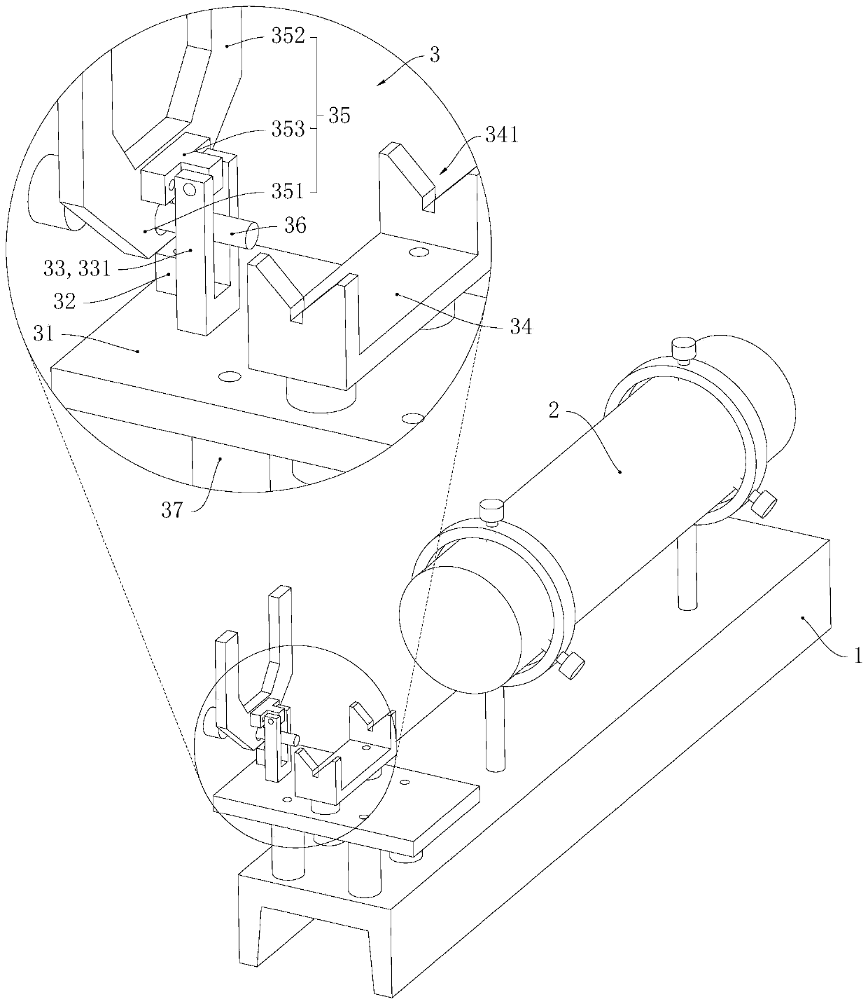
[0027] Please refer to Figure 1 to Figure 2 , the aiming inspection device of this embodiment includes a detection table 1, a collimator 2 and a locking fixture 3 of this embodiment, the collimator 2 and the locking fixture 3 are all installed on the detection table 1, and the axis of the collimator 2 The direction is along the Y-axis direction, the collimator 2 and the locking fixture 3 are distributed along the Y-axis direction, and the locking fixture 3 clamps the locking scope 4 .

[0028] Please refer to Figure 1 to Figure 2 , the locking fixture 3 includes an installation base 31, a hinged frame 33, a positioning tooth clamp 34, a clamp arm 35 and an adjustment assembly, the adjustment assembly includes a support block 32 and an adjustment bolt 36, the installation base 31 is fixed on the detection table 1, and the positioning teeth clamp 34 and the hinged frame 33 a...


PUM


Abstract

The invention relates to the field of equipment used for inspecting collimation devices. A locking clamp comprises a mounting base body, a hinge frame, a positioning tooth clamp, a clamping arm and anadjusting assembly; the adjusting assembly comprises a bearing block and a fastening part, the positioning tooth clamp and the hinge frame are fixed to the mounting base body, the bearing block is adjustably mounted on the mounting base body, the clamping arm is hinged to the hinge frame, the positioning tooth clamp, the hinge frame and the bearing block are distributed in the first direction, the hinging axis of the clamping arm and the hinge frame is in the second direction, the first direction is perpendicular to the second direction, the clamping arm comprises a limiting pressing clampingsection located above the positioning tooth clamp and a locking segment located above the bearing block, a clamping position is formed between the limiting pressing clamping section and the positioning tooth clamp, the fastening part is adjustably mounted on the locking segment, or the fastening part is adjustably mounted on the bearing block, and the adjusting direction of the fastening part isin the spacing direction of the locking segment and the bearing block. Locking and unlocking of the locking clamp can be rapidly achieved, and the accuracy of locking of a sighting telescope can be improved.

Description

technical field [0001] The invention relates to the field of equipment for checking aiming devices, in particular to a locking fixture and an aiming checking device. Background technique [0002] The scope needs to be tested during the production process, and the scope needs to be accurately fixed at the set position of the aiming test device during the aiming test. [0003] In order to fix the scope accurately, generally speaking, the process of locking and unlocking the scope will be complicated, and the process of locking and unlocking the scope will take a long time, which is not conducive to improving production efficiency. . Contents of the invention [0004] One of the objectives of the present invention is to provide a locking fixture with simple and fast locking and unlocking operations and accurate locking and fixing positions. [0005] In order to achieve the above object, the locking fixture provided by the present invention includes a mounting base, a hinged...

Claims


Application Information

Patent Timeline
Patent Type & Authority Applications(China)
IPC IPC(8): B25B11/00F41G1/54
CPCB25B11/00F41G1/54
Inventor 薛衍明黄合林
Owner 珠海天羿精密仪器有限公司
Learn More