
Large-bearing high-precision laser cladding workbench

A technology of laser cladding and workbench, which is applied in the direction of metal material coating process and coating, which can solve the problem that the laser cladding workbench cannot be applied to large workpieces.

Pending Publication Date: 2020-12-29
江苏珠峰光电科技有限公司
View PDF0 Cites 0 Cited by
  • Summary
  • Abstract
  • Description
  • Claims
  • Application Information

AI Technical Summary

Problems solved by technology

[0004] In order to solve the problem that the existing laser cladding workbench cannot be applied to some large workpieces, the present invention provides a large load-bearing and high-precision laser cladding workbench, in addition to the rotation control at both ends of the workbench for fixing the workpiece device and fixing device, and at least one supporting device is arranged between the two. The setting of the supporting device is conducive to more stable fixing of workpieces with large mass and volume, so that it is convenient to apply laser cladding to some high-quality For large and bulky workpieces, at the same time, the rotation control device, supporting device and fixing device are all slidably fixed on the table base, and the spacing of each part can be adjusted according to the length of the workpiece

Method used


Image

  • Large-bearing high-precision laser cladding workbench
  • Large-bearing high-precision laser cladding workbench
  • Large-bearing high-precision laser cladding workbench

Examples


Embodiment Construction

[0049] The present invention is described in further detail now in conjunction with accompanying drawing. These drawings are all simplified schematic diagrams, which only illustrate the basic structure of the present invention in a schematic manner, so they only show the configurations related to the present invention.

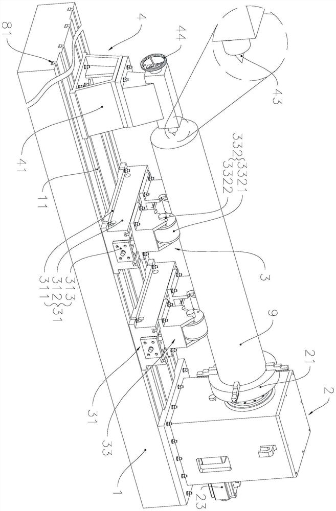
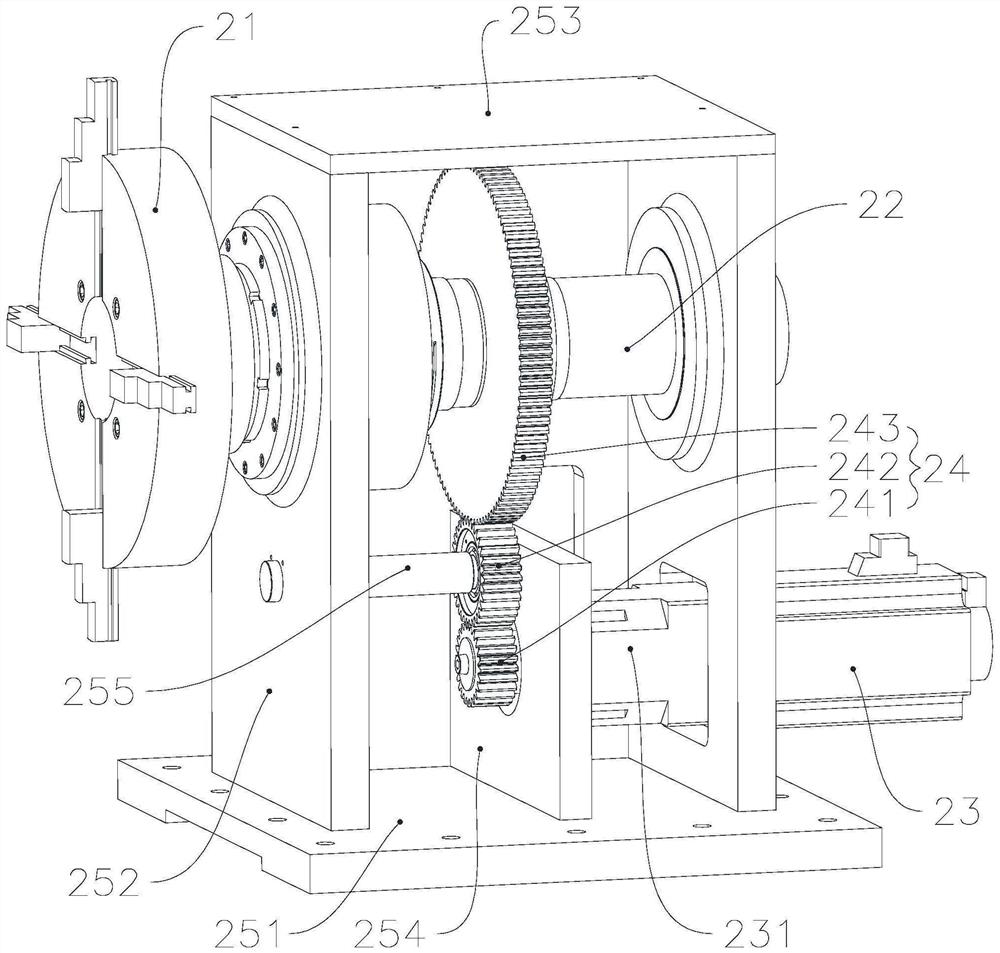
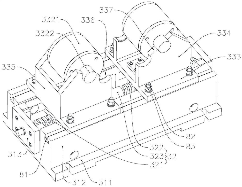
[0050] A laser cladding workbench with large load and high precision, such as figure 1 As shown, it includes a workbench base 1, a rotation control device 2 slidably fixed on the workbench base 1 in turn, at least one supporting device 3 and a fixing device 4, a workpiece 9 is placed on the supporting device 3, and one end is fixed on the On the rotation control device 2 , the rotation of the workpiece 9 is controlled by the rotation fixing device 4 , and the other end is in contact with the fixing device 4 , and the workpiece 9 is clamped by the cooperation of the fixing device 4 and the rotation control device 2 . The workbench of the present application, i...


PUM

PropertyMeasurementUnit
diameteraaaaaaaaaa

Abstract

The invention relates to the technical field of laser cladding workbenches, in particular to a large-bearing high-precision laser cladding workbench which comprises a workbench base, a rotation control device, at least one bearing device and a fixing device, and the rotation control device, the bearing device and the fixing device are sequentially fixed to the workbench base in a sliding mode. A workpiece is arranged on the bearing device, one end is fixed on the rotation control device, rotation of the workpiece is controlled through a rotation fixing device, the other end is in contact withthe fixing device, and the workpiece is clamped through cooperation of the fixing device and the rotation control device. According to the laser cladding workbench, the rotation control device and thefixing device which are used for fixing the workpiece are arranged, and the bearing device is further arranged between the rotation control device and the fixing device, so that a large-mass and large-size workpiece can be fixed more stably, and laser cladding can be applied to a large-scale workpiece conveniently. Meanwhile, the rotation control device, the bearing device and the fixing device are all fixed to the workbench base in a sliding mode, and the distance between all the parts can be adjusted according to the length of the workpiece.

Description

technical field [0001] The invention relates to the technical field of laser cladding workbenches, in particular to a laser cladding workbench with large load and high precision. Background technique [0002] Laser cladding refers to placing the selected coating material on the surface of the substrate to be clad in different ways, and then irradiating it with laser to melt it and a thin layer on the surface of the substrate at the same time, and form a very low dilution after rapid solidification. The surface coating is metallurgically combined with the substrate, a process method that significantly improves the wear resistance, corrosion resistance, heat resistance, oxidation resistance and electrical properties of the base surface, and cladding of high-performance and high-strength alloys on the basis of cheap metals Layer to achieve the purpose of surface modification or repair, which not only meets the requirements for the specific properties of the material surface, bu...

Claims


Application Information

Patent Timeline
Patent Type & Authority Applications(China)
IPC IPC(8): C23C24/10
CPCC23C24/103
Inventor 葛伟伟陆轩然施飞马俊傅康蒋芬军胡一鸣姜萍
Owner 江苏珠峰光电科技有限公司
Learn More