Well washing valve capable of achieving forward and reverse circulating well washing

A technology for reverse circulation well flushing and well flushing valve, which is applied in the direction of flushing wellbore, wellbore/well components, earth-moving drilling, etc., can solve the problem of difficult to meet the needs of downhole tubing cleaning, and achieves simple structure, simple operation and convenience. effect used

Pending Publication Date: 2020-01-10
SINOPEC SSC +1
View PDF0 Cites 2 Cited by
  • Summary
  • Abstract
  • Description
  • Claims
  • Application Information

AI Technical Summary

Problems solved by technology

[0002] Oil well flushing is one of the important tasks in the daily management of the oil production team, in order to reduce and remove the wax and scale of the downhole tubing, clean the inner wall of the tubing, improve the flow conditions of the wellbore, and increase the oil production efficiency; the well flushing operations include positive flushing and reverse flushing There are two different basic methods. When flushing the well, the flushing fluid enters from the tubing and returns from the casing. In reverse flushing, the fluid enters from the casing and returns from the tubing. The flushing valve is a commonly used downhole valve. It can not only ensure the smoothness of the normal oil outlet channel during oil well production, but also provide the well flushing fluid channel for well flushing during well flus

Method used


Image

  • Well washing valve capable of achieving forward and reverse circulating well washing
  • Well washing valve capable of achieving forward and reverse circulating well washing
  • Well washing valve capable of achieving forward and reverse circulating well washing

Examples


Embodiment Construction

[0032] In the following, the present invention will be further described in conjunction with the accompanying drawings and specific embodiments. It should be noted that, on the premise of not conflicting, the various embodiments or technical features described below can be combined arbitrarily to form new implementations. example. Unless otherwise specified, the materials and equipment used in this embodiment can be purchased from the market.

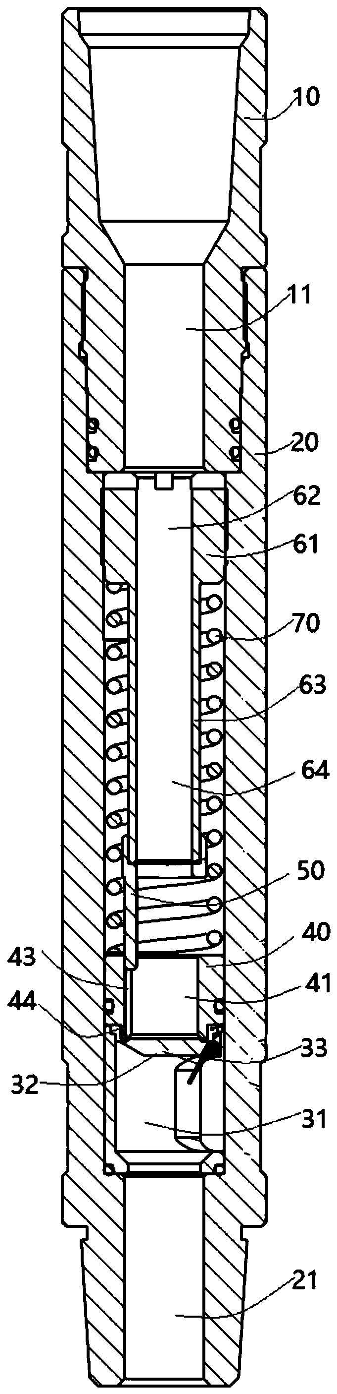
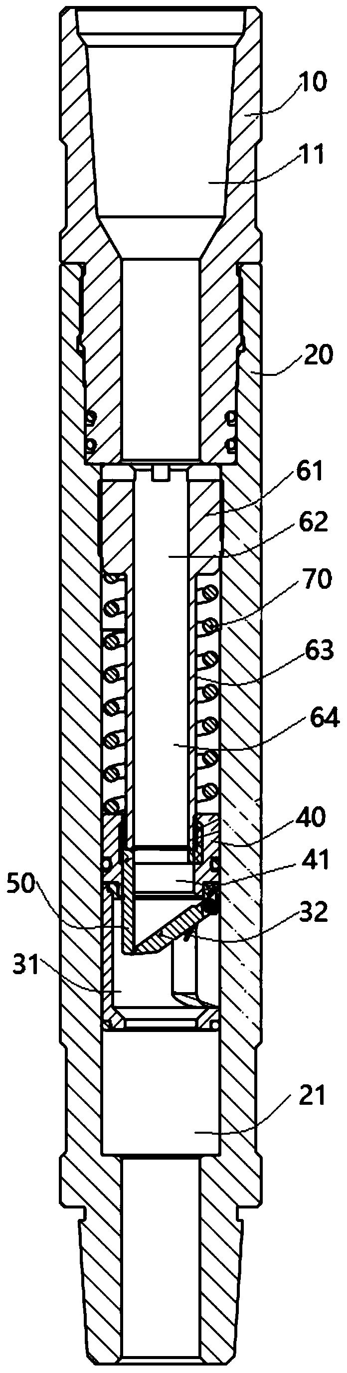
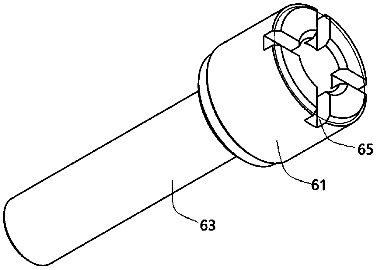
[0033] see Figure 1-4 , a well flushing valve capable of realizing positive and negative circulation flushing, comprising an upper joint part 10 and a lower joint part 20 sleeved on the lower part of the upper joint part 10;

[0034] The upper joint part 10 is provided with a hollow cavity 11 axially penetrating its top and bottom, and the lower joint part 20 is provided with an installation cavity 21 axially penetrating its top and bottom, and the installation cavity 21 communicates with the hollow cavity 11; the upper joint part 10 ...


PUM


Abstract

The invention discloses a well washing valve capable of achieving forward and reverse circulating well washing. The well washing valve comprises an upper joint portion and a lower joint portion connected to the lower portion of the upper joint portion in a sleeved manner. A hollow cavity axially penetrating through the top and the bottom of the upper joint portion is arranged on the upper joint portion. A mounting cavity axially penetrating through the top and the bottom of the lower joint portion is arranged on the lower joint portion. The mounting cavity communicates with the hollow cavity.A valve body is mounted in the mounting cavity and is provided with a valve cavity axially penetrating through the top and the bottom of the valve body, and the valve cavity communicates with the mounting cavity. A valve plate is arranged at the top of the valve body. The valve plate can be opened or closed, and therefore the valve cavity and the mounting cavity communicate or are blocked. A valvecontrol device is further mounted in the mounting cavity and is mounted on the upper portion of the valve plate, and the valve control device can open the valve plate. According to the well washing valve, forward circulating well washing can be achieved, and under the normal well pressure, pressure or fluid in a well is blocked; when the pressure in the well reaches a certain value, reverse circulating well washing can be achieved; and in the processes of forward and reverse circulating well washing, normal downhole work is not influenced.

Description


Claims


Application Information

Patent Timeline
Owner SINOPEC SSC
Why Eureka
Try Eureka