
Video data transmission method and device

A technology of video data transmission and video networking, applied in the field of video networking, can solve the problems of large video display time difference, video display delay, high load, etc., to achieve the effect of ensuring synchronous playback and reducing delay

Active Publication Date: 2020-01-10
VISIONVERA INFORMATION TECH CO LTD
View PDF10 Cites 0 Cited by
  • Summary
  • Abstract
  • Description
  • Claims
  • Application Information

AI Technical Summary

Problems solved by technology

[0003] Therefore, when multiple channels of video are displayed on a split screen in the terminal, when requesting video streams, the client and the server will perform signaling interaction through the Session Initiation Protocol when requesting each video stream to confirm the transmission of each video stream, The parameters required for playback, after which the server will establish a connection with the client to split the video stream. Since multiple videos need to be confirmed separately, the video of the front channel should be confirmed and displayed first, and the video of the rear channel should be confirmed first. After confirming and displaying later, when multi-channel video is played in split screen, the display time difference of each channel is large and the delay is problematic. Even if it is a multi-core and multi-threaded design framework, multiple threads process different video requests at the same time. Each thread The video request load undertaken is still high, resulting in delays in video display

Method used


Image

  • Video data transmission method and device
  • Video data transmission method and device
  • Video data transmission method and device

Examples


Embodiment Construction

[0058] In order to make the above objects, features and advantages of the present invention more comprehensible, the present invention will be further described in detail below in conjunction with the accompanying drawings and specific embodiments.

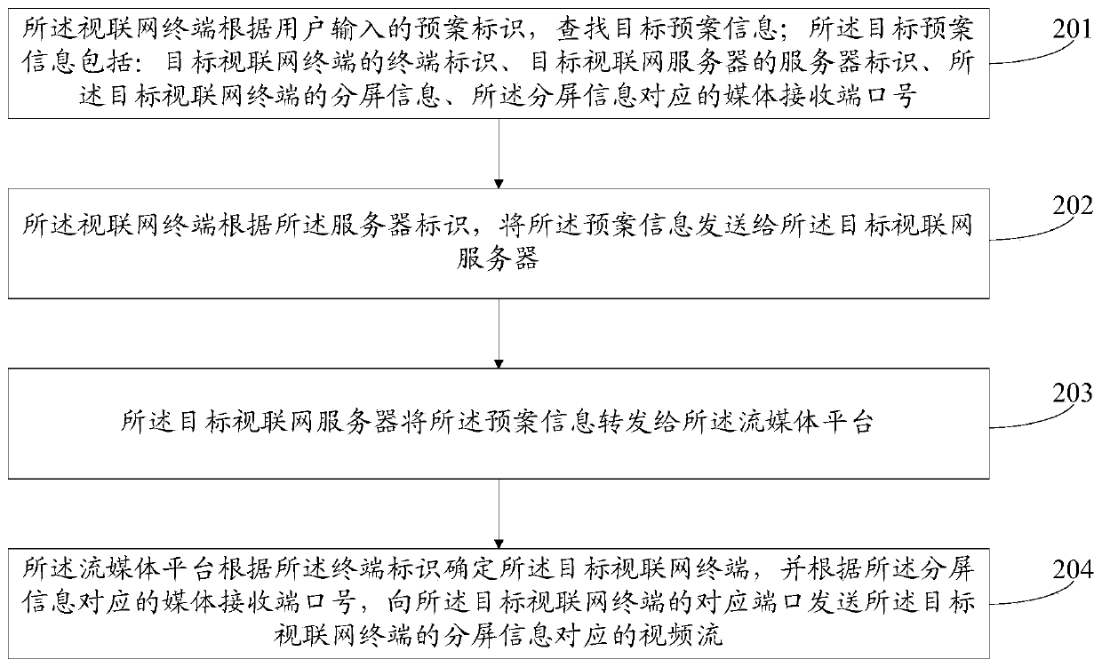
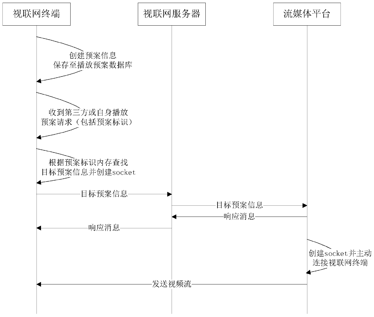
[0059] Based on the characteristics of the Internet of Things, figure 1 It is a schematic diagram of the data transmission process during a video data transmission of the present invention, such as figure 1 As shown, one of the core ideas of the embodiments of the present invention is proposed. Following the protocol of the Internet of Vision, the Internet of Vision loads the plan information from the plan database, and saves the created plan information in the plan database. The Internet of View terminal according to the user input Plan identification, find the corresponding target plan and then send the target plan to the Internet of Things server, the Internet of Things server forwards the target plan to the streaming media pla...


PUM


Abstract

The embodiment of the invention provides a video data transmission method and device. The method is applied to the articulated naturality web and comprises the steps that an articulated naturality webterminal searches target plan information according to a plan identifier input by a user, and the target plan information comprises a terminal identifier of a target articulated naturality web terminal, a server identifier of a target articulated naturality web server, split screen information of the target articulated naturality web terminal and a media receiving end port number corresponding tothe split screen information; the articulated naturality web terminal sends the plan information to the target articulated naturality web server according to the server identifier; the target articulated naturality web server forwards the plan information to a streaming media platform; and the streaming media platform determines the target articulated naturality web terminal and sends a corresponding video stream to the target articulated naturality web terminal according to the media receiving port number. In the embodiment of the invention, by sending the plan information, the split screeninformation and the receiving end port number in the current video playing are confirmed, and the problem of playing delay caused by the fact that video sources, parameter information and the like ofmultiple paths of videos need to be confirmed one by one in split screen playing is avoided.

Description

technical field [0001] The invention relates to the technical field of video networking, in particular to a video data transmission method and device. Background technique [0002] The Internet of View is a real-time network that can realize real-time transmission of high-definition video across the network, and promote video services to high-definition video. At present, when video data is transmitted in the Internet of Vision, each channel of video involved needs to undergo multiple signaling interactions to confirm the path of video playback. [0003] Therefore, when multiple channels of video are displayed on a split screen in the terminal, when requesting video streams, the client and the server will perform signaling interaction through the Session Initiation Protocol when requesting each video stream to confirm the transmission of each video stream, The parameters required for playback, after which the server will establish a connection with the client to split the v...

Claims


Application Information

Patent Timeline
Patent Type & Authority Applications(China)
IPC IPC(8): H04L29/06H04L29/08
CPCH04L65/1066H04L69/162H04L67/1095H04L65/75H04L67/568
Inventor 张涛涛沈军王洪超么学佳
Owner VISIONVERA INFORMATION TECH CO LTD
Learn More