Aluminum foil mylar die cutting device

A technology of aluminum foil mylar and die-cutting, which is applied in the directions of transportation and packaging, metal processing, and coiling strips, etc. It can solve the problems of not being able to flatten the front part of the cutting, cutting with a single cutter, and not being able to improve the leveling effect of die-cutting, etc. To achieve the effect of ensuring cleanliness, improving efficiency and avoiding pollution of the operating environment

Inactive Publication Date: 2020-01-14
湖北富和冠电子材料有限公司
View PDF0 Cites 1 Cited by
  • Summary
  • Abstract
  • Description
  • Claims
  • Application Information

AI Technical Summary

Problems solved by technology

[0003] During the production and processing of aluminum foil Mylar, a die-cutting device is needed to effectively cut the aluminum foil Mylar. The existing die-cutting device is only a single cutter for cutting, but it cannot effectively cut the part before cutting. Flattening can not improve the leveling effect of die-cutting, so a new type of aluminum foil Mylar die-cutting device is designed to solve the above problems

Method used


Image

  • Aluminum foil mylar die cutting device
  • Aluminum foil mylar die cutting device
  • Aluminum foil mylar die cutting device

Examples


Embodiment 1

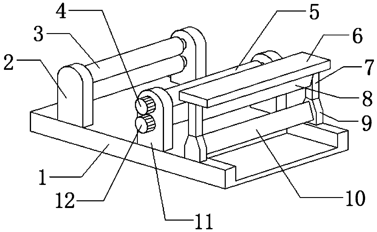
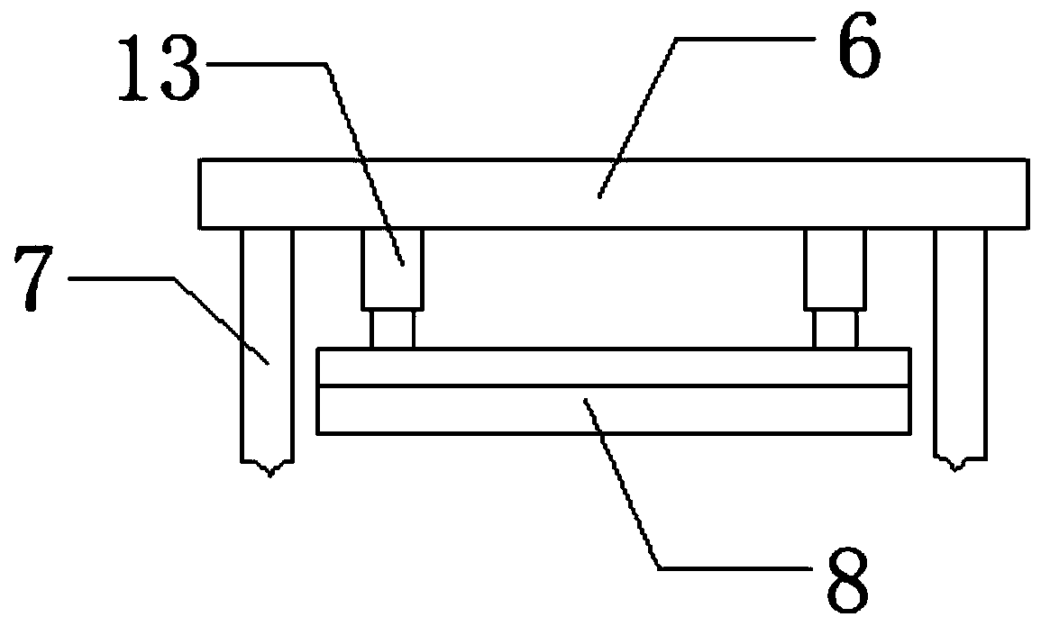
[0023] refer to Figure 1-2 , an aluminum foil Mylar die-cutting device, including a support base 1, the outer walls of both ends of the top side of the support base 1 are connected with a first splint 2 by bolts, and two first splints 2 are connected by two bearings. The first pressure roller 3, the outer walls at both ends of the top center of the support base 1 are connected with the second clamping plate 11 vertically arranged by bolts, and two rotating rods 15 are connected by bearings between the two second clamping plates 11, two The peripheral outer wall of the rotating rod 15 is all sleeved with the second pressure roller 5, and the top outer wall of one end of one of the second clamping plates 11 is connected with the first rotating motor 4 by bolts, and the outer wall of the bottom of one end of the second clamping plate 11 is connected by bolts. The second rotating motor 12, and the outer walls at one end of the two rotating rods 15 are respectively connected with ...

Embodiment 2

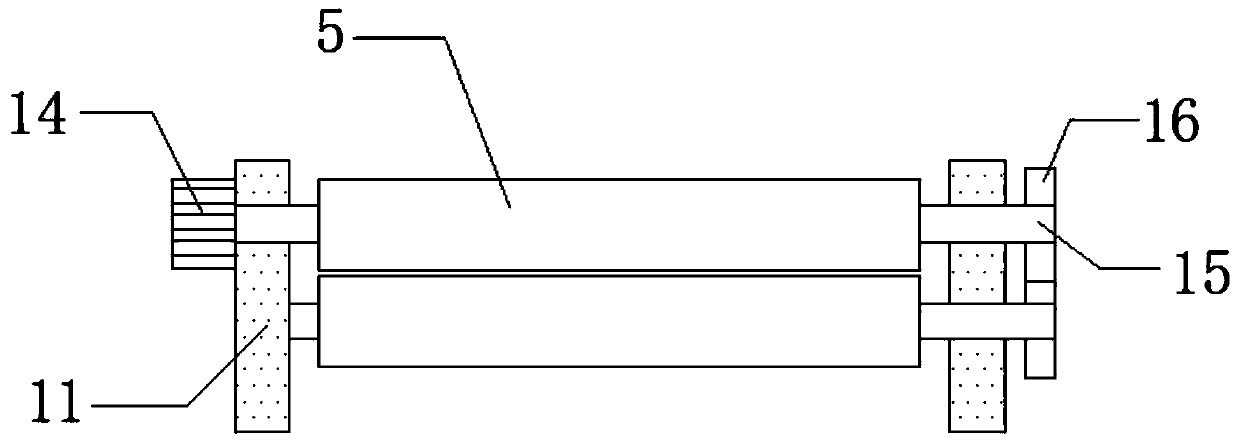
[0026] refer to Figure 1-3 , a Mylar die-cutting device for aluminum foil, the first rotating motor 4 and the second rotating motor 12 are replaced by a third rotating motor 14, and the output shaft of the third rotating motor 14 is connected to one end of one of the rotating rods 15 through a bolt The outer walls are connected, the outer walls of the other ends of the two rotating rods 15 are connected with gears 16 by bolts, and the two gears 16 are meshed with each other, the third rotating motor 14 is electrically connected with a switch through a wire, and the switch is electrically connected to the power supply through a wire. Connected, the third rotating motor 14 drives one of the rotating rods 15 to rotate, and then the two meshing gears 16 drive the other rotating rod 15 to rotate, and then the two second pressure rollers 5 can rotate in opposite directions to drive the aluminum foil Mylar The movement realizes the continuous die-cutting effect, and the use of the d...


PUM


Abstract

The invention discloses an aluminum foil mylar die cutting device. A supporting base is included. First clamping plates are fixedly arranged on the outer walls of the two ends of one side of the top of the supporting base. Two first pressing rollers are connected between the two first clamping plates through bearings. The outer walls of the two ends of the center of the top of the supporting baseare fixedly provided with vertically-arranged second clamping plates, and two rotation rods are connected between the two clamping plates through bearings. According to the provided aluminum foil mylar die cutting device, through the arrangement of the first clamping plates and the second clamping plates, the two first pressing rollers are arranged between the two first clamping plates, the two second pressing rollers are arranged between the two second clamping plates, aluminum foil mylar needing to be subjected to die cutting can penetrate through the two first pressing rollers and the two second pressing rollers, and the aluminum foil mylar can be effectively flattened; and meanwhile, the aluminum foil mylar can be straightened between the first pressing rollers and the second pressingrollers, and the die cutting effect is improved.

Description

technical field [0001] The invention relates to the technical field of aluminum foil mylar processing, in particular to an aluminum foil mylar die-cutting device. Background technique [0002] Aluminum foil Mylar is based on metal aluminum foil, glued to polyester tape (usually PE, TPP, etc.) The changing trend of aluminum foil with a thickness of 4 μm is gradually increasing, depending on the application industry and end use. [0003] During the production and processing of aluminum foil Mylar, a die-cutting device is needed to effectively cut the aluminum foil Mylar. The existing die-cutting device is only a single cutter for cutting, but it cannot effectively cut the part before cutting. Flattening can not improve the leveling effect of die-cutting, so a new type of aluminum foil Mylar die-cutting device is designed to solve the above problems. Contents of the invention [0004] The purpose of the present invention is to solve the shortcoming existing in the prior art...

Claims


Application Information

Patent Timeline
Patent Type & Authority Applications(China)
IPC IPC(8): B26F1/44B26F1/38B29C53/18B26D7/18B65H23/26
CPCB26D7/18B26F1/38B26F1/44B29C53/18B65H23/26
Inventor 刘超
Owner 湖北富和冠电子材料有限公司
Why Eureka
Try Eureka