Protracted pile frame platform

A technology of stretching and pile frame, which is applied in the direction of sheet pile wall, building, foundation structure engineering, etc. It can solve the problems of increasing the cost of turning, increasing the difficulty and cost of transshipment, and the external dimension of the pile driver platform cannot be changed.

Pending Publication Date: 2020-01-14
JIANGSU JUWEI MACHINERY
View PDF0 Cites 0 Cited by
  • Summary
  • Abstract
  • Description
  • Claims
  • Application Information

AI Technical Summary

Problems solved by technology

[0003] The existing pile frame platform is actually a frame structure with platform legs composed of longitudinal beams and beams fixedly connected to each other. Due to the fixed structure, the overall size of the pile driver platform cannot be changed
With the continuous enlargement and complexity of construction projects, more and more various construction equipment are carried on the pile driver platform, and the structural size of the pile driver platform becomes larger and larger, and the pile with large structural size The pile driver platform brings a lot of inconvenience to the movement and transportation, especially when the pile machinery is transferred to another site, due to the restrictions of the road overrun and overload transportation regulations, it is difficult for the pile driver platform with a large structural size to pass through the convenient road. If the transportation method is turned, it will not only increase the cost of turning, but also increase the difficulty and cost of transshipment

Method used


Image

  • Protracted pile frame platform
  • Protracted pile frame platform
  • Protracted pile frame platform

Examples


Embodiment Construction

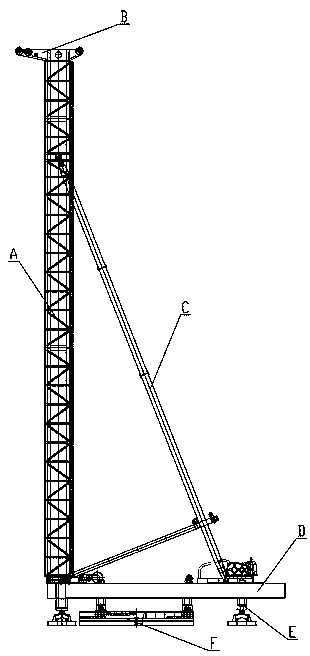
[0020] figure 1 Shown is the existing common walking mobile pile frame structure, the pile frame includes a pile frame platform D, the pile frame platform D is a frame structure composed of longitudinal beams and beams fixedly connected to each other, the longitudinal beams and beams It is welded by section steel or steel plate. A column A is installed on the upper plane of the pile frame platform D, a pulley frame B is arranged on the top of the column A, and a brace is connected between the upper plane of the pile frame platform D and the column A. Rod C, platform leg E is installed on the lower plane of the pile frame platform D, the platform leg E is a hydraulic cylinder, the cylinder body of the hydraulic cylinder is fixedly installed on the pile frame platform D, and the protruding end of the piston rod of the hydraulic cylinder Hinged on the walking chassis F, the walking movement of the entire platform can be realized through the alternate expansion and contraction of ...


PUM


Abstract

The invention discloses a protracted pile frame platform. The protracted pile frame platform comprises cross beams, longitudinal beams and support legs; the support legs are fixedly mounted at the twoends of the cross beams; the cross beams are hinged with the longitudinal beams; at least two cross beams and at least two longitudinal beams are provided; and the cross beams and the longitudinal beams are mutually hinged to form a parallelogram mechanism. Middle longitudinal beams are hinged to the cross beams, and are in parallel to the longitudinal beams. The middle longitudinal beams adopt frame fixed structures; end beams are fixedly arranged at one ends of the middle longitudinal beams; and end beam support legs are fixedly mounted at the two ends of the end beams, and are hydraulic cylinders. The middle longitudinal beams are hinged with the cross beams through hinge connecting pins. Hinge holes are formed in the longitudinal beams, and movably sleeve cylinder blocks of the hydraulic cylinders of the support legs. The protracted pile frame platform can change the boundary dimension, and is convenient to transfer and transport and particularly suitable for pile frame structuresof large pile machines.

Description

technical field [0001] The invention relates to a pile frame of a pile driver in a pile machine, in particular to the improvement of the platform structure of the pile frame of a pile driver. Background technique [0002] Pile machinery is widely used in various pile foundation constructions. Pile machinery often needs a pile frame for supporting, guiding, lifting and shifting, so the pile frame is an important part of pile machinery. At present, the pile frame of the pile driver is mainly composed of a pile frame column, a strut, a pulley frame at the top of the column, a hoist, a pile frame platform and a walking chassis, etc. Various working parts such as the pile frame column, support rod, and hoist are all set on the pile frame platform , while the pile frame platform is supported on the walking chassis, by means of the walking chassis pile frame platform can carry and move the working equipment and working parts on it. [0003] The existing pile frame platform is actu...

Claims


Application Information

Patent Timeline
IPC IPC(8): E02D7/14E02D7/16E02D7/06
CPCE02D7/06E02D7/14E02D7/16
Inventor 许清张静孟春明冯启阳王小娟
Owner JIANGSU JUWEI MACHINERY
Why Eureka
Try Eureka