A fast cutting device for building steel pipes

A technology for fast cutting and steel pipes, which is applied in the direction of shearing devices, attachments of shearing machines, metal processing equipment, etc. It can solve the problems of inability to cut to fixed lengths, easy sore arms, etc., and achieve the effect of fast cutting and simple operation

Active Publication Date: 2021-10-26
河南省翔鸿建筑工程有限公司
View PDF7 Cites 0 Cited by
  • Summary
  • Abstract
  • Description
  • Claims
  • Application Information

AI Technical Summary

Problems solved by technology

[0005] In order to overcome the disadvantages that the workers have been holding down the cutting machine and moving down at a constant speed to cut off the pipeline, the workers’ arms are prone to soreness after cutting the steel pipe for a long time, and they cannot perform fixed-length cutting. The technical problem to be solved is: to provide a The steel pipe is clamped, and the construction steel pipe quick cutting device can automatically adjust the fixed length

Method used


Image

  • A fast cutting device for building steel pipes
  • A fast cutting device for building steel pipes
  • A fast cutting device for building steel pipes

Examples


Embodiment 1

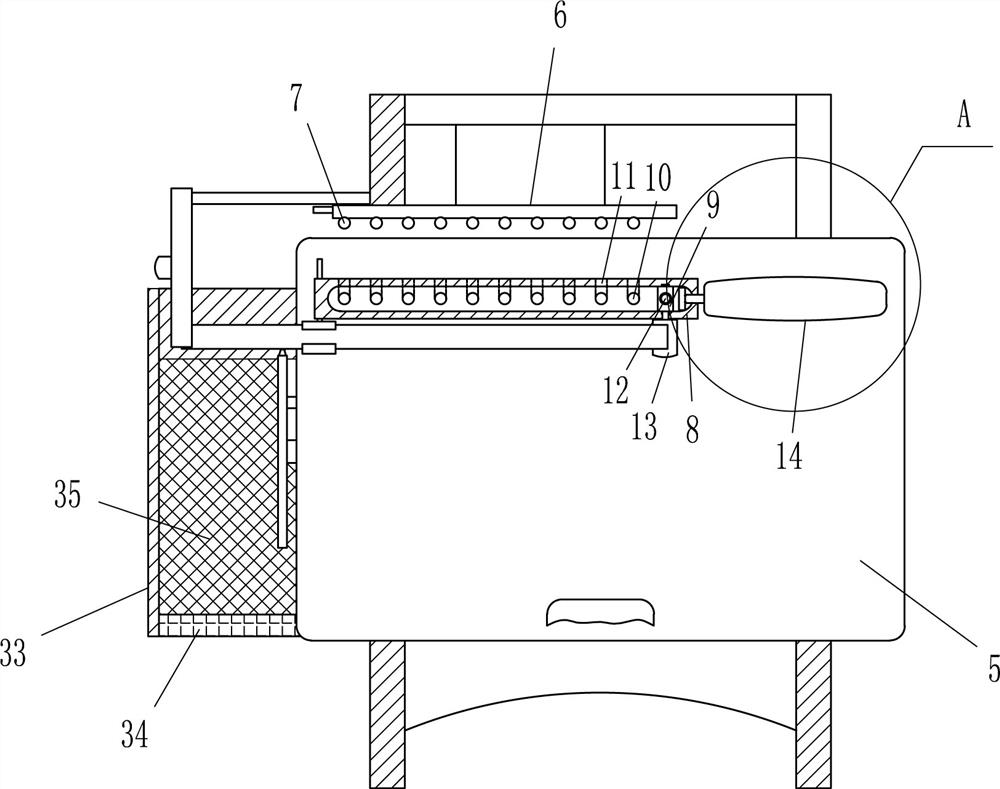
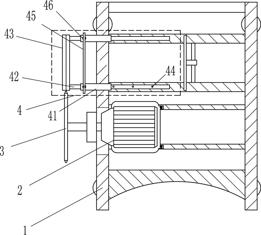
[0021] Such as Figure 1-2 As shown, a rapid cutting device for building steel pipes includes a frame 1, a motor 2, a cutting knife 3, a positioning device 4, a mounting plate 5, a mounting frame 6, a push rod 7, a slide plate 8, a sliding block 9, and an insertion rod 12 , pushing block 13 and pushing device 14, motor 2 is installed in the middle part of frame 1, and cutting knife 3 is arranged on the output shaft of motor 2, and positioning device 4 is installed on frame 1, and positioning device 4 is positioned at motor 2 rear side, and positioning The device 4 is used for adjusting and positioning the required cutting length of the steel pipe. The top of the frame 1 is slidingly provided with a mounting plate 5, the front side of the mounting plate 5 is embedded with a handle, the rear side of the frame 1 is provided with a mounting frame 6, and the mounting frame 6 The front side is evenly provided with ejector rods 7, and the rear side of the top of the mounting plate 5 ...

Embodiment 2

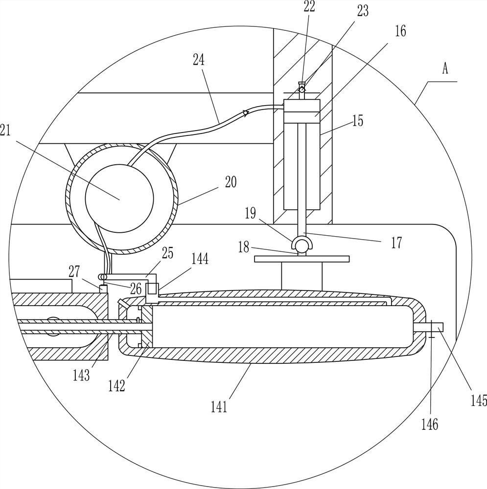
[0025] Such as figure 2 , image 3 and Figure 4As shown, on the basis of Embodiment 1, the pushing device 14 includes a first cylinder 141, a first piston 142, a through pipe 143, an air intake pipe 144, an air outlet pipe 145, a valve 146, a block 147, an air outlet 148, The second piston 149, the moving rod 1410, the push block 1411 and the air outlet branch pipe 1412, the rear side of the top of the mounting plate 5 is provided with a first cylinder 141, and the first cylinder 141 is movably provided with a first piston 142, the first piston 142 The middle part is embedded with a through pipe 143, and the left part of the rear side of the first cylinder 141 is provided with an intake pipe 144. A valve 146 is arranged on the air outlet pipe 145, a stopper 147 is arranged on the left part of the first cylinder body 141, an air outlet port 148 is arranged on the rear side of the left part of the first cylinder body 141, and a second piston 149 is movable in the through pip...

Embodiment 3

[0029] Such as figure 1 and Figure 5 As shown, on the basis of Embodiment 2, it also includes a mounting block 28, a fixed block 29, a moving block 30, a connecting rod 31 and an elastic member 32, and the rear left part of the mounting plate 5 is set by bolts There is a mounting block 28, the mounting block 28 is provided with a fixed block 29, the front side of the fixed block 29 is provided with a through hole, a connecting rod 31 is movably arranged in the through hole, and a moving block 30 is arranged on the front side of the connecting rod 31, An elastic member 32 is disposed between the moving block 30 and the connecting rod 31 , and the elastic member 32 is a tension spring.

[0030] The staff places the steel pipe between the fixed block 29 and the movable block 30, and one end of the steel pipe rests on the push block 13. When the mounting plate 5 moves forward, the elastic member 32 resets and drives the movable block 30 to move backward. The fixed clamping bloc...


PUM


Abstract

The invention relates to a cutting device, in particular to a fast cutting device for building steel pipes. The technical problem to be solved is how to provide a quick cutting device for construction steel pipes that can clamp the steel pipes and can automatically adjust the fixed length. A rapid cutting device for building steel pipes, including a frame, a motor, a cutting knife, a positioning device, a mounting plate, a mounting frame, a push rod, etc.; a motor is installed in the middle of the frame, and a cutting knife is arranged on the output shaft of the motor. A positioning device is installed on it. The present invention achieves the effect of clamping the steel pipe and automatically adjusting the fixed length. The present invention clamps the steel pipe through the cooperation of the fixed block and the moving block, and the loosening and clamping of the steel pipe can be realized by continuously moving the mounting plate back and forth. The action of tightening and pushing realizes the equidistant adjustment of the steel pipe, and the operation is simple. The staff only need to grasp the handle of the installation plate and move back and forth, which can realize the rapid cutting of the steel pipe, which is safe and convenient.

Description

technical field [0001] The invention relates to a cutting device, in particular to a fast cutting device for building steel pipes. Background technique [0002] Construction steel pipes, with hollow sections, whose length is much longer than the diameter or circumference of steel, can be divided into circular, square, rectangular and special-shaped steel pipes according to the cross-sectional shape; according to the material, they can be divided into carbon structural steel pipes, low alloy structural steel pipes, alloy Steel pipes and composite steel pipes; divided into pipelines, engineering structures, thermal equipment, petrochemical industry, machinery manufacturing, geological drilling, high-pressure equipment steel pipes, etc. according to their uses; seamless steel pipes according to production technology And welded steel pipes, of which seamless steel pipes are divided into two types: hot-rolled and cold-rolled (drawn), and welded steel pipes are divided into straig...

Claims


Application Information

Patent Timeline
Patent Type & Authority Patents(China)
IPC IPC(8): B23D19/00B23D33/00B23D33/02
CPCB23D19/00B23D33/00B23D33/02
Inventor 廖志强
Owner 河南省翔鸿建筑工程有限公司
Why Eureka
Try Eureka