
Hydraulic centering device and method for assembling and connecting segmented crankshaft

A centering device and a segmented technology, which is applied in metal processing, metal processing equipment, manufacturing tools, etc., can solve the problems of segmented crankshaft connections that are difficult to center and difficult to meet the requirements, so as to reduce the intensity and difficulty of the operation, The effect of improving efficiency and improving accuracy

Inactive Publication Date: 2020-01-17
CSSC MES DIESEL
View PDF7 Cites 1 Cited by
  • Summary
  • Abstract
  • Description
  • Claims
  • Application Information

AI Technical Summary

Problems solved by technology

Compared with the traditional integral crankshaft, the segmented crankshaft needs to perfectly splice the front and rear crankshafts in the machine base. The concentricity of the connecting holes of the segmented crankshaft is usually required to be less than 0.02mm, and it is difficult to adjust it manually. Meet the requirements, so the connection centering of the segmented crankshaft has always been a difficult problem in the industry

Method used


Image

  • Hydraulic centering device and method for assembling and connecting segmented crankshaft
  • Hydraulic centering device and method for assembling and connecting segmented crankshaft
  • Hydraulic centering device and method for assembling and connecting segmented crankshaft

Examples


Embodiment Construction

[0025] The hydraulic centering device and method for assembly and connection of segmented crankshafts according to the present invention will be further described in detail below in conjunction with the accompanying drawings and specific embodiments, but the protection scope of the present invention should not be limited thereby.

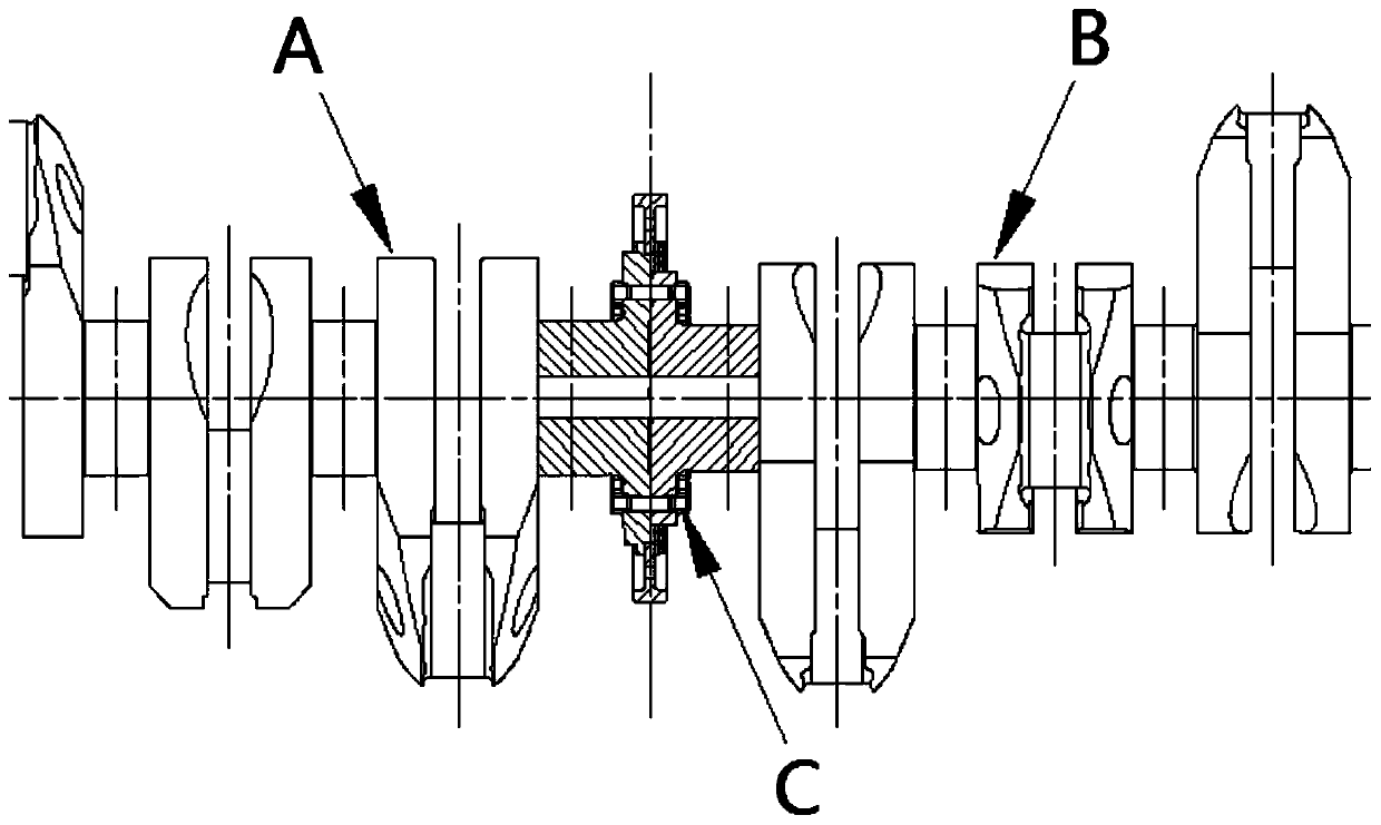
[0026] The present invention is used for the assembly, connection and centering operation of the segmented crankshaft. The segmented crankshaft includes a front crankshaft A and a rear crankshaft B. See image 3 , the front end crankshaft A and the rear end crankshaft B are provided with connection holes at the joints, and the hydraulic centering device C is installed in the connection holes.

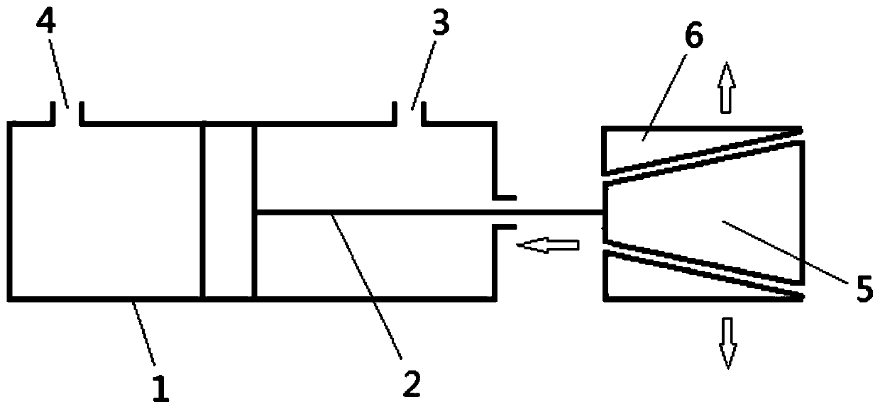
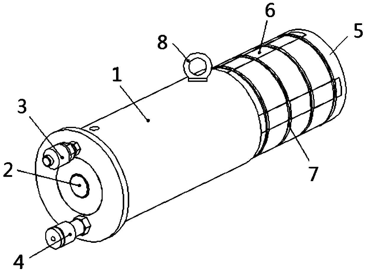
[0027] see figure 2 , the hydraulic centering device for assembling and connecting the segmented crankshaft includes a hydraulic cylinder, a wedge shaft 5 and a plurality of wedges 6 .

[0028] The hydraulic cylinder includes a cylinder block 1 and a piston...


PUM


Abstract

The invention discloses a hydraulic centering device for assembling and connecting a segmented crankshaft. The segmented crankshaft comprises a front-end crankshaft and a rear-end crankshaft, connecting holes are formed in the connecting positions of the front-end crankshaft and the rear-end crankshaft, and the hydraulic centering device is installed in the connecting holes and comprises a hydraulic oil cylinder, a wedge shaft and a plurality of wedge blocks, wherein the wedge shaft is connected with the hydraulic oil cylinder, a plurality of inclined plane grooves along the axial direction are formed in the outer circle of the wedge shaft, the plurality of wedge blocks are respectively embedded in the plurality of inclined plane grooves, and the inclined planes of the wedge blocks and theinclined planes of the inclined plane grooves are in fit and relatively slide; the hydraulic oil cylinder drives the wedge shaft to move along the axial direction, the wedge blocks move around in theradial direction under the action of the inclined plane of the wedge shaft, radial outward pushing expansion force is exerted on the connecting holes, and the front-end crankshaft and the rear-end crankshaft are automatically centered. According to the hydraulic centering device, the axial pulling force of the hydraulic oil cylinder is converted into the radial pushing force of the wedge blocks towards the periphery, so that automatic centering of the front-end crankshaft and the rear-end crankshaft is realized, the operation strength and difficulty are reduced, and the centering precision and efficiency of the segmented crankshaft connecting holes are improved.

Description

technical field [0001] The invention relates to an assembly process of a marine low-speed diesel engine, in particular to a hydraulic centering device and method for segmented crankshaft assembly and connection, and belongs to the technical field of marine diesel engine manufacturing. Background technique [0002] As the core component of the engine, the crankshaft has very high installation requirements. In recent years, with the continuous improvement of the power of marine diesel engines, the use of segmented crankshafts has become more and more common. When the number of main engine cylinders is greater than 8 cylinders, segmented crankshafts are usually used. Compared with the traditional integral crankshaft, the segmented crankshaft needs to perfectly splice the front and rear crankshafts in the machine base. The concentricity of the connecting holes of the segmented crankshaft is usually required to be less than 0.02mm, and it is difficult to adjust it manually. Meet...

Claims


Application Information

Patent Timeline
IPC IPC(8): B23P19/10
CPCB23P19/10
Inventor 袁林海张飞黄晗笑柳军
Owner CSSC MES DIESEL
Learn More