Robot gripper multi-functional test device
A technology for multi-functional testing and testing devices, which is applied to measuring devices, machine gear/transmission mechanism testing, and electrical devices, etc., can solve the problems of high cost, single function, complex structure, etc., and achieve low cost, multiple functions, and reduced The effect of work intensity and difficulty
- Summary
- Abstract
- Description
- Claims
- Application Information
AI Technical Summary
Problems solved by technology
Method used
Image
Examples
specific Embodiment approach 1
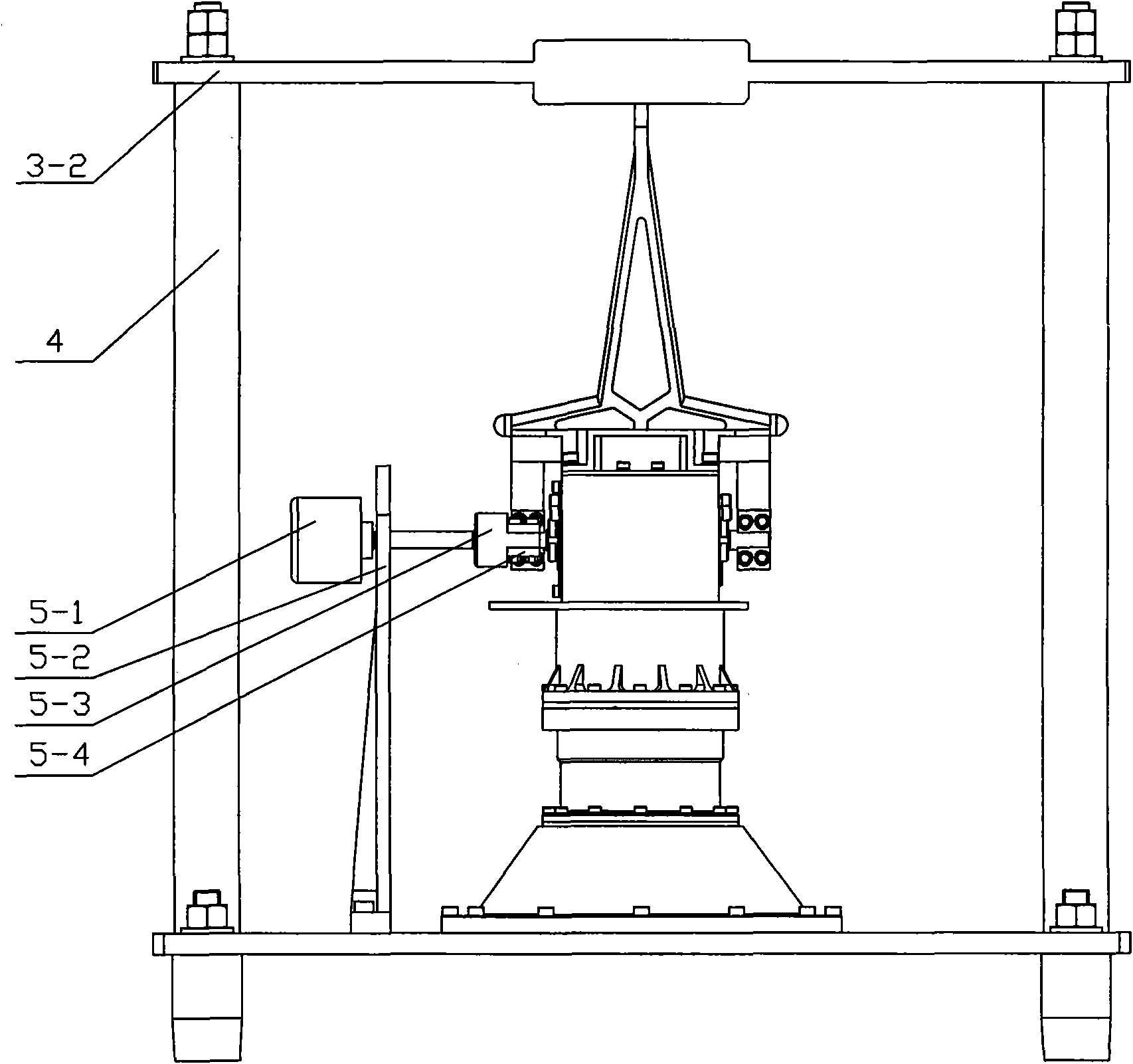
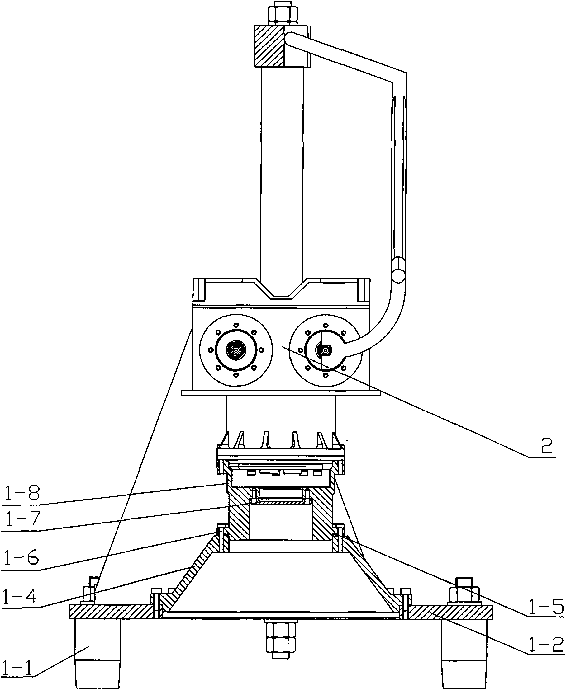
[0010] Specific implementation mode one: combine figure 1 and figure 2 Describe this embodiment, the test device of this embodiment consists of a support seat assembly, a positioning plate 3-2, two columns 4, a code wheel 5-1, a code wheel fixing plate 5-2, a connecting shaft 5-3 and a splint 5 -4; the support seat assembly is composed of four support legs 1-1, the installation plate 1-2, the installation flange 1-4 and the protection dustproof seat assembly; the four corners of the lower end surface of the installation plate 1-2 Each is provided with a supporting leg 1-1 detachably connected with the mounting plate 1-2, and the mounting flange 1-4 is arranged on the upper end surface of the mounting plate 1-2 and is detachably connected with it (connected by screws 1-6 Dust-proof seat 1-8, gasket 1-5 are connected with mounting flange 1-4), the protective dust-proof seat assembly is set on the mounting flange 1-4 and is detachably connected with it, and the positioning plat...
specific Embodiment approach 2
[0011] Specific implementation mode two: combination figure 1 and figure 2 Describe this embodiment, the protective dustproof seat assembly of this embodiment is made up of protective cover 1-7 and dustproof seat 1-8; Dustproof seat 1-8 is arranged on the upper end surface of mounting flange 1-4 and with it Detachable connection, the lower end surface of the dust-proof seat 1-8 is provided with an inner shoulder hole, the upper end surface of the dust-proof seat 1-8 is provided with a through hole, the inner shoulder hole of the dust-proof seat 1-8 and the dust-proof The through holes of the seat 1-8 are connected, and the protective cover 1-7 is arranged on the inner shoulder end face of the inner shoulder hole of the dustproof seat 1-8, and the protective cover 1-7 is detachably connected with the dustproof seat 1-8. During the measurement, the hand claw 2 to be tested is placed on the dust-proof seat 1-8. By connecting the robot gripper with the protective cover and the ...
specific Embodiment approach 3
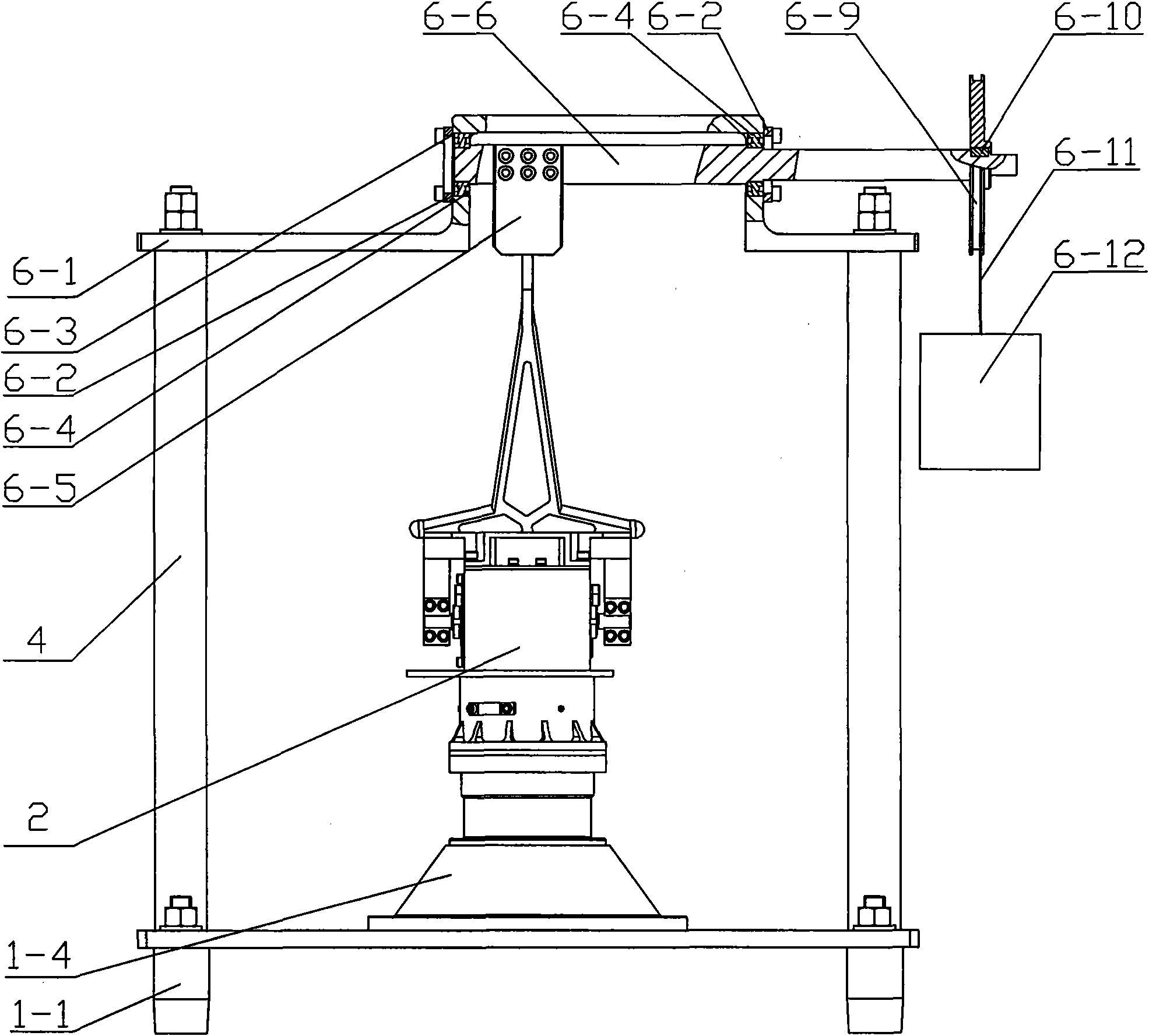
[0013] Specific implementation mode three: combination Figure 3 ~ Figure 7 Describe this embodiment, the test device of this embodiment consists of a support seat assembly, a positioning plate 3-2, two columns 4, a bearing seat 6-1, two bearing caps 6-2, a gasket 6-3, two Bearing 6-4, force plate 6-5, transmission shaft 6-6, pulley 6-9, steel wire 6-11 and weight 6-12; the support base assembly consists of four support legs 1-1, mounting plate 1-2. The installation flange 1-4 is composed of a protective dust-proof seat assembly; each of the four corners of the lower end surface of the installation board 1-2 is provided with a support leg 1-2 detachably connected with the installation board 1-2 1. The mounting flange 1-4 is set on the upper end surface of the mounting plate 1-2 and is detachably connected with it (the dustproof seat 1-8, the gasket 1-5 and the mounting flange 1-4 are connected by screws 1-6 connection), the protective dustproof seat assembly is set on the mou...
PUM
 Abstract
Description
Claims
Application Information
 - R&D
- Intellectual Property
- Life Sciences
- Materials
- Tech Scout
- Unparalleled Data Quality
- Higher Quality Content
- 60% Fewer Hallucinations
Browse by: Latest US Patents, China's latest patents, Technical Efficacy Thesaurus, Application Domain, Technology Topic, Popular Technical Reports.
© 2025 PatSnap. All rights reserved.Legal|Privacy policy|Modern Slavery Act Transparency Statement|Sitemap|About US| Contact US: help@patsnap.com


