Eureka AIR delivers breakthrough ideas for toughest innovation challenges, trusted by R&D personnel around the world.

Bearing support frame clamping device and clamping method thereof

A technology of bearing support frame and clamping device, applied in the direction of workpiece clamping device, manufacturing tools, etc., can solve problems such as clamping deformation, achieve the effect of solving clamping deformation and ensuring machining accuracy

Pending Publication Date: 2020-01-17
SHENZHEN AOWEIDE ELECTROMECHANICAL CO LTD
View PDF0 Cites 0 Cited by
  • Summary
  • Abstract
  • Description
  • Claims
  • Application Information

AI Technical Summary

Problems solved by technology

[0004] In view of the shortcomings of the prior art above, the purpose of the present invention is to provide a bearing support frame clamping device and its clamping method, so as to solve the problem that the existing clamps deform the bearing support parts

Method used


Image

  • Bearing support frame clamping device and clamping method thereof
  • Bearing support frame clamping device and clamping method thereof
  • Bearing support frame clamping device and clamping method thereof

Examples


Embodiment Construction

[0030] The invention provides a bearing support frame clamping device and a clamping method thereof. In order to make the object, technical solution and effect of the present invention more clear and definite, the present invention will be further described in detail below with reference to the accompanying drawings and examples. It should be understood that the specific embodiments described here are only used to explain the present invention, not to limit the present invention.

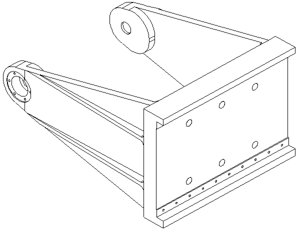
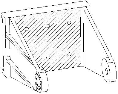
[0031] Such as figure 1 The bearing supports of the type shown are generally divided into casting, aging, rough machining, artificial aging, finishing and other stages according to the usual process route. In this embodiment, it is assumed that the bearing supports have undergone rough machining and artificial aging. image 3 as shown ( image 3 With figure 1 Corresponding reverse side, to show the reference of the shadow surface used later), the shadow surface has been processed into a reference...


PUM


Abstract

The invention discloses a bearing support frame clamping device and a clamping method thereof. The bearing support frame clamping device is used for clamping a processed part and includes a clamp body, pneumatic clamping components and a control component. A clamping surface is arranged at one end of the clamp body, the clamping surface abuts against the inner surface of the processed part, and side clamping surfaces of the clamp body are in contact with bearing arms on the two sides of each processed part; the control component is arranged at the other end of the clamp body and is connected with the pneumatic clamping components in a pneumatic manner, the control component is used for controlling the pneumatic clamping components to be switched between the clamping state and the looseningstate; and the pneumatic clamping components are arranged on the top, the side concave face and the bottom of the clamp body and correspondingly clamp the top, a hole and the bottom of a bearing refined hole of the processed part in the clamping state, and the bearing refined hole of the processed part is loosened in the loosening state. Clamping with the pneumatic manner is carried out, the problems of clamping deformation, cocking and the like are solved, and the machining accuracy is ensured.

Description

technical field [0001] The invention relates to the technical field of mechanical processing, in particular to a clamping device for a bearing support frame and a clamping method thereof. Background technique [0002] In the structural parts of optical communication, some types of bearing supports (such as figure 1 Shown) Because of its irregular structure, high precision requirements, and difficult clamping, if there is no suitable clamping device during mass production, it will be difficult to meet customer needs in terms of quality and efficiency. At the same time, in order to ensure the processing accuracy, such bearing supports must be subjected to a separate finishing process for key dimensions after rough machining to meet actual use requirements, such as figure 2 Various size requirements shown ( figure 2 The size data in is just an example, it can be changed according to the actual implementation, and it is not limited here); for batch processing, ordinary vise ...

Claims


Application Information

Patent Timeline
Patent Type & Authority Applications(China)
IPC IPC(8): B25B11/00
CPCB25B11/00
Inventor 邓燕军
Owner SHENZHEN AOWEIDE ELECTROMECHANICAL CO LTD
Why Eureka
Eureka Blog
Learn More