
Experimental device for simulating single-joint dynamic variable load variable inertia of an industrial robot

A technology for industrial robots and experimental devices, applied in manipulators, manufacturing tools, etc., can solve the problems of complex structure, difficult control, and difficult to realize dynamic change of inertia, and achieve the effects of easy adjustment, convenient installation and simple operation.

Pending Publication Date: 2020-01-17
ZHEJIANG UNIV OF TECH
View PDF0 Cites 0 Cited by
  • Summary
  • Abstract
  • Description
  • Claims
  • Application Information

AI Technical Summary

Problems solved by technology

[0005] The purpose of the present invention is to solve the defects of the existing load simulation device that the dynamic change of inertia is difficult to realize or the structure is complex, the load change is not real-time or the control is difficult, and the functions of variable inertia and variable load cannot be simultaneously provided, and a single joint for simulating industrial robots is proposed The experimental device of dynamic variable inertia and variable load can synthesize the dynamic change of inertia, meet various complex loads, and briefly simulate joint motion conditions

Method used


Image

  • Experimental device for simulating single-joint dynamic variable load variable inertia of an industrial robot
  • Experimental device for simulating single-joint dynamic variable load variable inertia of an industrial robot
  • Experimental device for simulating single-joint dynamic variable load variable inertia of an industrial robot

Examples


Embodiment Construction

[0038] The present invention will be further described below in conjunction with accompanying drawing:

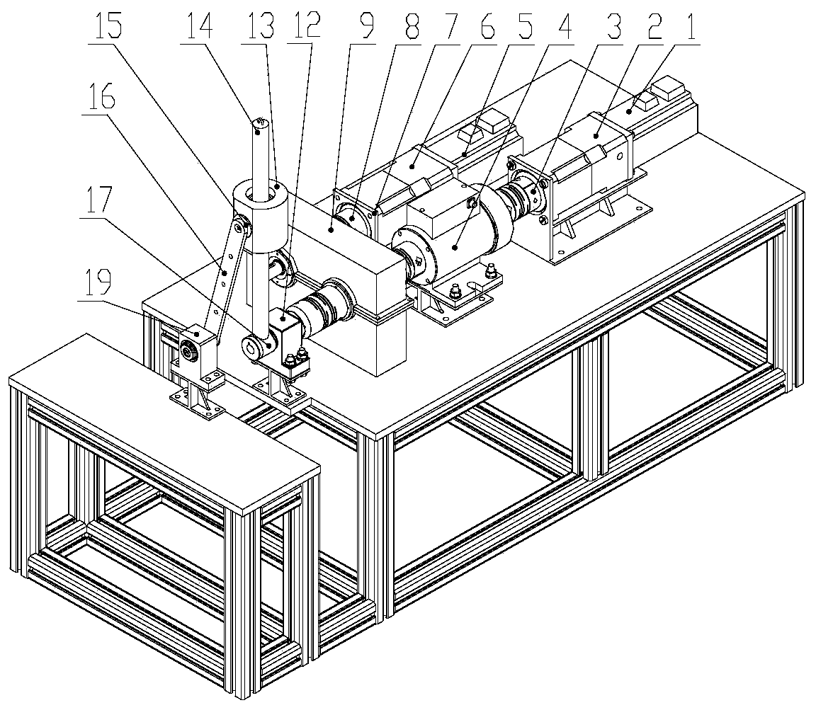
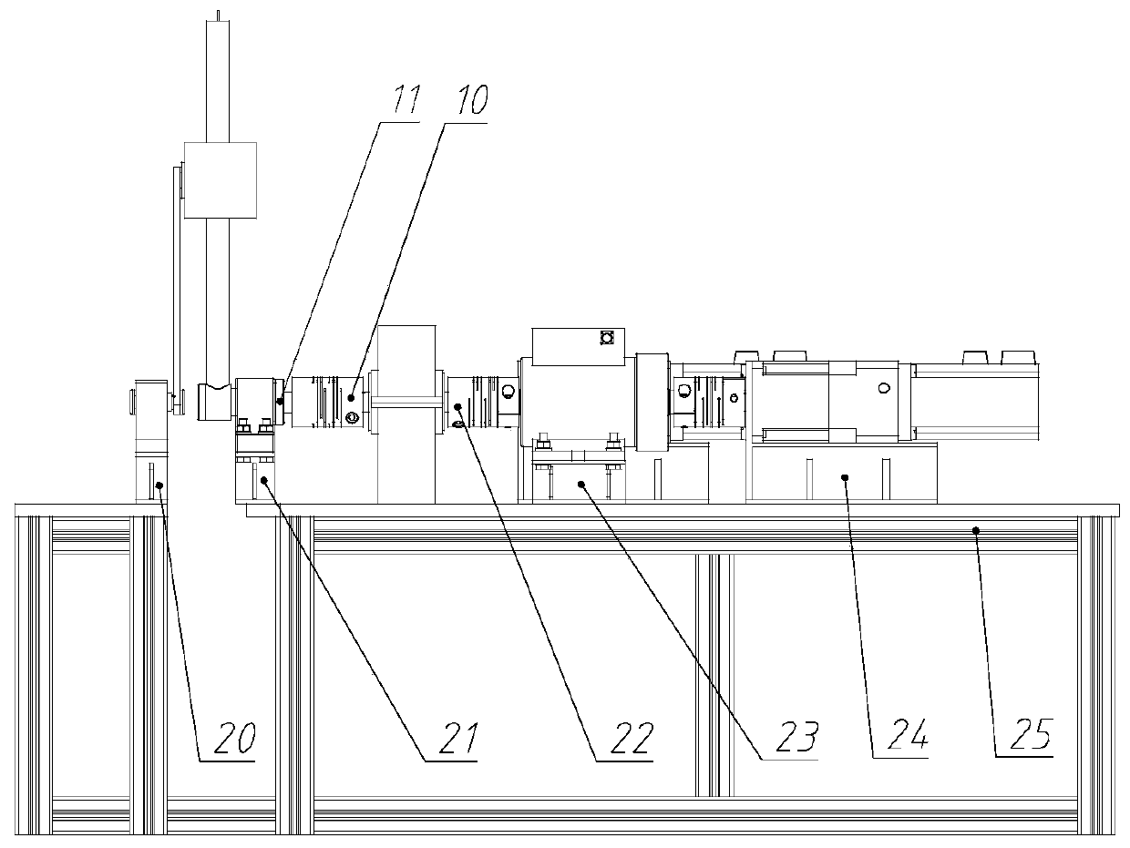
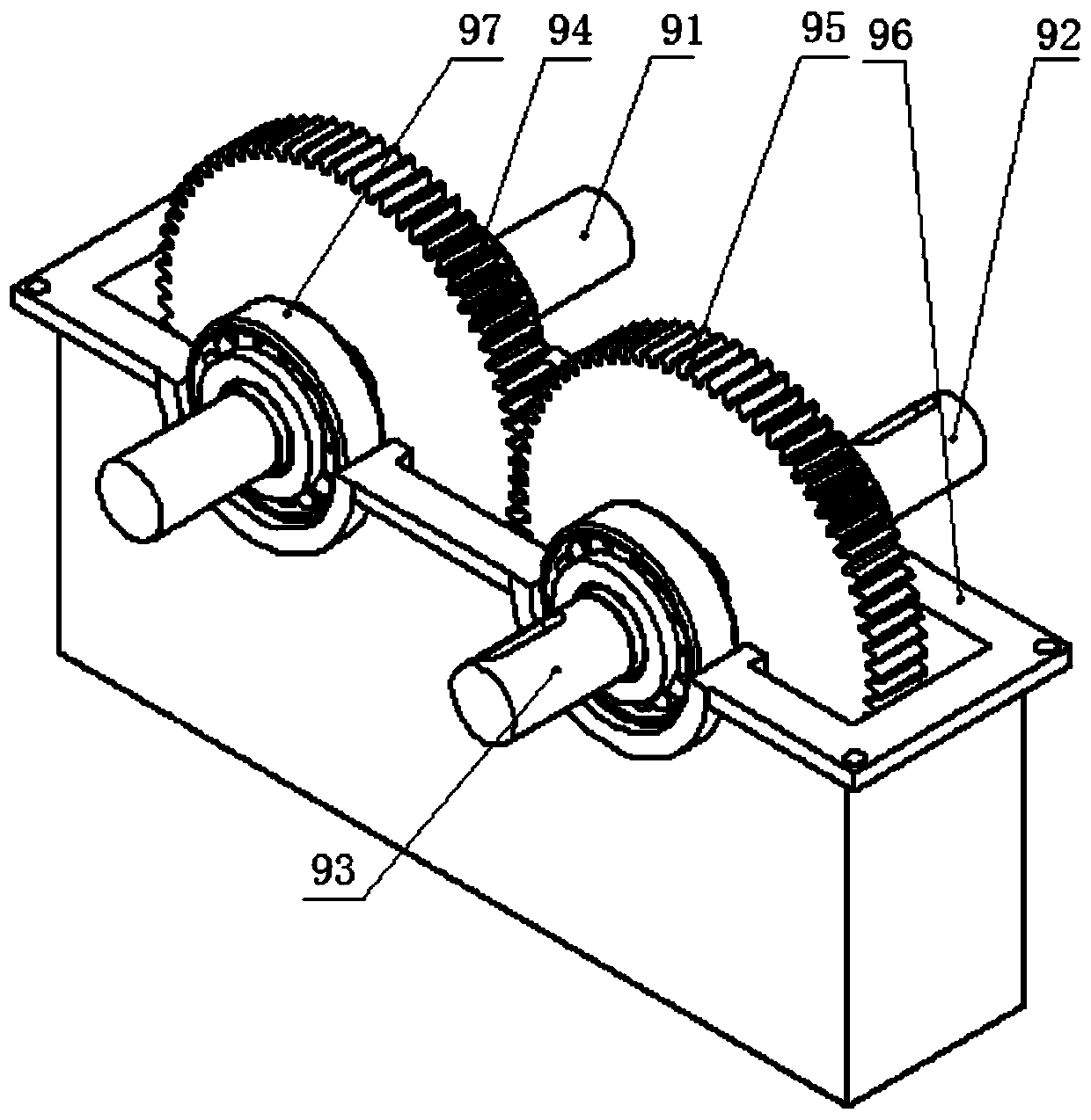
[0039] like Figure 1-10 As shown, an experimental device for simulating the dynamic variable load and variable inertia of industrial robot joints, the first frame 25, the second frame 26, the first input servo motor 1, the first reducer 2, the first coupling 3, Dynamic torque sensor 4, gear transmission box 9, second coupling 22, angle sensor 11, first double bearing housing 12, variable inertia lever arm 14, third coupling 10, rotating shaft 17, second input servo motor 5 , the second reducer 6, the fourth coupling 8, the mass slider 13, the swing arm 16, the second double bearing housing 19, the rotating shaft 18, the first support base 21, the second support base 23, the third support base 24. The fourth support base 7 and the fifth support base 20.

[0040] Both the first input servo motor 1 and the first reducer 2 are fixed on the third support base 24, and the outp...


PUM


Abstract

The invention discloses an experimental device for simulating single-joint dynamic variable load variable inertia of an industrial robot. The experimental device comprises a first rack, a second rack,a first input servo motor, a first speed reducer, a first coupler, a dynamic torque sensor, a gear transmission box, a second coupler, an angle sensor, a first double-bearing pedestal, a variable inertia lever arm, a third coupler, a rotating shaft, a second input servo motor, a second speed reducer, a fourth coupler, a mass sliding block, a swing arm, a second double-bearing pedestal, a rotatingshaft, a first supporting base, a second supporting base, a third supporting base, a fourth supporting base and a fifth supporting base. According to the experimental device, inertia and load dynamicchanges are integrated, and a control system can simulate various joint motion working conditions.

Description

technical field [0001] The invention relates to the field of joint servo control system testing, in particular to the field of experimental devices with variable load and variable inertia, and more specifically, an experimental device for simulating the dynamic variable load and variable inertia of a single joint of an industrial robot. Background technique [0002] At present, experiments on servo motor control algorithms directly on the joints of industrial robots need to overcome many technical difficulties, such as the high cost of the mechanical parts of industrial robots and the difficulty of data collection, so the research is mostly limited to the software simulation stage and semi-simulation stage. During the motion of industrial robot joints, there are working conditions such as real-time changes in inertia and sudden load changes. For such problems, in order to evaluate and design the control algorithm for effective experiments, the experimental simulation device ...

Claims


Application Information

Patent Timeline
Patent Type & Authority Applications(China)
IPC IPC(8): B25J19/00
CPCB25J19/0095
Inventor 裘锦霄张光盛郑颖姜伟季行健王晨裘信国
Owner ZHEJIANG UNIV OF TECH
Learn More