
Mold guide structure

A mold guide and guide column technology, applied in the mold field, can solve the problems of polluting the mold, lack of residual oil collection function, etc., and achieve the effect of improving the sealing effect, avoiding random flow, and convenient installation

Inactive Publication Date: 2020-01-17
方金兰
View PDF0 Cites 2 Cited by
  • Summary
  • Abstract
  • Description
  • Claims
  • Application Information

AI Technical Summary

Problems solved by technology

[0003] In the prior art, guide posts are usually used for mold guidance, and lubricating oil is usually applied to the guide posts in order to reduce friction, but the existing mold guide structure lacks the function of collecting residual oil, and the lubricating oil applied on the guide posts tends to flow freely pollute the mold, so a mold-guiding structure is needed to solve the above-mentioned problems

Method used


Image

  • Mold guide structure
  • Mold guide structure

Examples


Embodiment approach

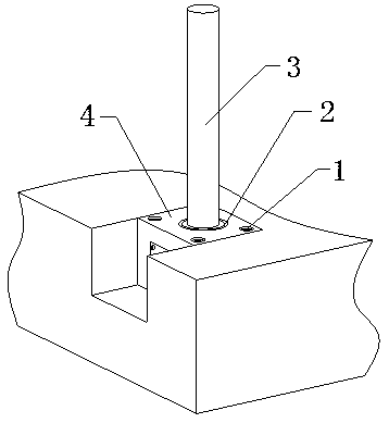
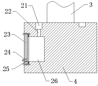
[0019] Specific implementation: when in use, insert hexagon socket bolts in the four sets of countersunk holes 1, and use the socket bolts to connect the base 4 with the mold. When it is necessary to lubricate the guide column 3, apply lubricating oil on the On the guide post 3, when there is more lubricating oil on the guide post 3, the lubricating oil flows down along the guide post 3 under its own gravity, and then flows into the annular groove 21, because the inner lower end surface of the annular groove 21 is high on the right and low on the left. The inclined surface, so the lubricating oil flowing into the annular groove 21 is collected on the left side of the annular groove 21, and then the lubricating oil flows into the groove 26 through the oil leakage port 22, because a cover plate 23 is installed on the left side of the groove 26, and the cover plate A sealing ring is installed on the right end of 23, so the lubricating oil will not flow out from the gap between the...


PUM


Abstract

The invention provides a mold guiding structure. The structure involves an annular groove, an oil leakage port, a cover plate, a rubber plug, an oil outlet and a groove, wherein the annular groove isformed in the upper end face of a base and is arranged on the outer side of a guide column, the groove is formed in the left end face of the base, the cover plate is installed on the inner left end face of the groove through an inner hexagonal bolt, the oil leakage port is formed in the lower end face inside the annular groove and communicates with the groove, the oil outlet is formed in the lowerside of the left end face of the cover plate, and the rubber plug is installed in the oil outlet. According to the structure, oil flowing down from the guide column is collected through the annular groove, so that the purpose of collecting the residual oil is achieved, and the influence of residual oil on the surface of a mold is reduced. The structure has a residual oil collecting function, is convenient to install and good in stability.

Description

technical field [0001] The invention relates to a mold guiding structure, which belongs to the technical field of molds. Background technique [0002] The mold guide can ensure the precise mold clamping of the movable mold and the fixed mold. When the mold is closed, it is guided by the guide mechanism first, and then the punch and the die are closed, which can avoid the collision and damage of the punch and die. Since the shape of the cavity is not necessarily symmetrical, the force of the melt on the wall of the cavity is also different. At this time, the guiding mechanism can bear a certain side pressure. [0003] In the prior art, guide posts are usually used for mold guidance, and lubricating oil is usually applied to the guide posts in order to reduce friction, but the existing mold guide structure lacks the function of collecting residual oil, and the lubricating oil applied on the guide posts tends to flow freely Contaminate the mold, so a mold guiding structure is ...

Claims


Application Information

Patent Timeline
Patent Type & Authority Applications(China)
IPC IPC(8): B29C33/00
CPCB29C33/00
Inventor 不公告发明人
Owner 方金兰
Learn More