A cavitation model correction method suitable for cavitation flow around moving boundaries

A cavitation model and dynamic correction technology, applied in the field of hydraulic machinery, can solve the problems of refined flow field information acquisition and high research cost, and achieve the effect of solving related engineering technical problems and improving prediction accuracy.

Active Publication Date: 2021-02-09
BEIJING INSTITUTE OF TECHNOLOGYGY
View PDF2 Cites 0 Cited by
  • Summary
  • Abstract
  • Description
  • Claims
  • Application Information

AI Technical Summary

Problems solved by technology

[0004] The purpose of the present invention is to solve the problem of large experimental research costs and less refined flow field information in hydraulic mechanical cavitation phenomena, and to provide a cavitation model correction method suitable for cavitation flow around dynamic boundaries , this method can improve the numerical prediction accuracy of the cavitation flow around the moving boundary

Method used


Image

  • A cavitation model correction method suitable for cavitation flow around moving boundaries
  • A cavitation model correction method suitable for cavitation flow around moving boundaries
  • A cavitation model correction method suitable for cavitation flow around moving boundaries

Examples


Embodiment 1

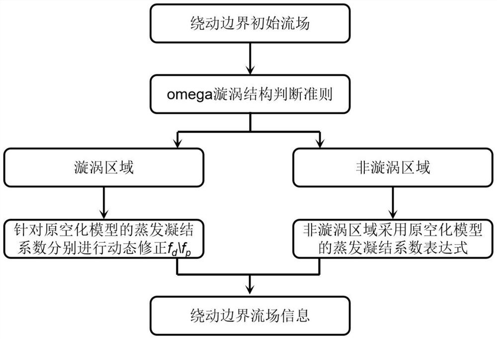
[0048] Figure 4 It is the numerical calculation domain around the dynamic hydrofoil, which includes the dynamic domain and the static domain. The rotation of the hydrofoil is realized by controlling the rotation of the dynamic domain. The hydrofoil is set to rotate at a uniform speed, and the rotational angular velocity is 0.35rad / s; The inlet is set as a velocity inlet with a flow rate of 5.5m / s; the outlet is a pressure outlet with a pressure of 21325pa. The vortex structure judgment criterion adopts omega, and the threshold A is set to 0.52.

[0049] Then calculate the global omega of the initial flow field according to the omega expression. When omega is greater than or equal to 0.52, it is a vortex area, and when omega is less than 0.52, it is a non-vortex area.

[0050] The cavitation model is chosen as the Kubota cavitation model, and the interphase transmission rate per unit volume is:

[0051]

[0052]

[0053] In the formula, α nuc is the gas nuclei volume ...


PUM


Abstract

The invention relates to a cavitation model correction method applicable to cavitation flow around dynamic boundaries, and belongs to the technical field of hydraulic machinery. The filter scale is defined by the criterion of the vortex structure, and the flow field is divided into the vortex area and the non-vortex area based on the filter scale; then the evaporation phase coefficient C of the cavitation model in the vortex area d Multiply by the evaporation phase dynamic correction factor f d , condensed phase coefficient C p Multiplied by the condensed phase dynamic correction factor f p , the cavitation model evaporation phase coefficient C in the non-vortex region d , condensed phase coefficient C p Keep original model values. Then the evaporation phase coefficient C d , condensed phase coefficient C p Bring it into the cavitation model mass transfer equation again to solve the cavitation flow field. The invention adopts the vortex structure as the filter scale, links the numerical prediction simulation with the cavitation flow field information, considers the influence of the dynamic boundary on the vapor-liquid two-phase mass transmission in the cavitation model, and greatly improves the prediction of the cavitation flow around the dynamic boundary precision.

Description

technical field [0001] The invention relates to a cavitation model correction method applicable to cavitation flow around dynamic boundaries, and belongs to the technical field of hydraulic machinery. Background technique [0002] In the study of hydraulic machinery, the additional force generated by the rotation and the disturbance of the static and dynamic components have an important impact on the turbulent flow process, the development of the boundary layer, and the temporal and spatial distribution of the flow structure. It is the focus and difficulty of the research. In the transient process of propeller, turbo pump, hydraulic turbine start-up and shutdown, runaway, load increase and decrease, etc., the transient flow in the transient process will change the effective angle of attack of the lifting surface, and its internal flow is complex and changeable, showing a strong Instability, especially under cavitation conditions, seriously affects the working performance of...

Claims


Application Information

Patent Timeline
Patent Type & Authority Patents(China)
IPC IPC(8): G06F30/17
Inventor 黄彪张孟杰刘涛涛吴钦王国玉
Owner BEIJING INSTITUTE OF TECHNOLOGYGY
Why Eureka
Try Eureka