
Printing nozzle

A technology of printing nozzles and screw pumps, applied in biochemical instruments, biochemical equipment and methods, coating devices, etc., can solve the problems of long time consumption, complicated disassembly process, and many disassembly steps, so as to reduce constraints and facilitate disassembly and assembly Efficient, less restrictive effect

Pending Publication Date: 2020-01-21
SICHUAN REVOTEK CO LTD
View PDF0 Cites 3 Cited by
  • Summary
  • Abstract
  • Description
  • Claims
  • Application Information

AI Technical Summary

Problems solved by technology

[0005] The inventor found that when the screw pump needs to be cleaned or replaced, the casing must be disassembled first using tools, and the screw pump and the motor must be taken out; , the disassembly process is complex and time-consuming

Method used


Image

  • Printing nozzle
  • Printing nozzle
  • Printing nozzle

Examples


Embodiment Construction

[0047] Combine below Figure 1 to Figure 7 The technical solution provided by the present invention is described in more detail.

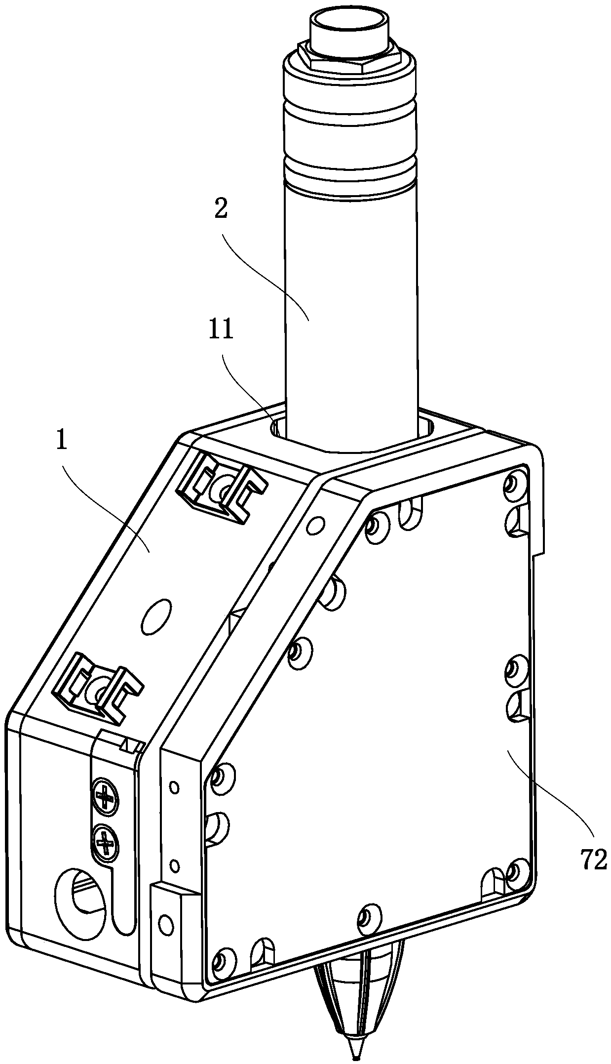
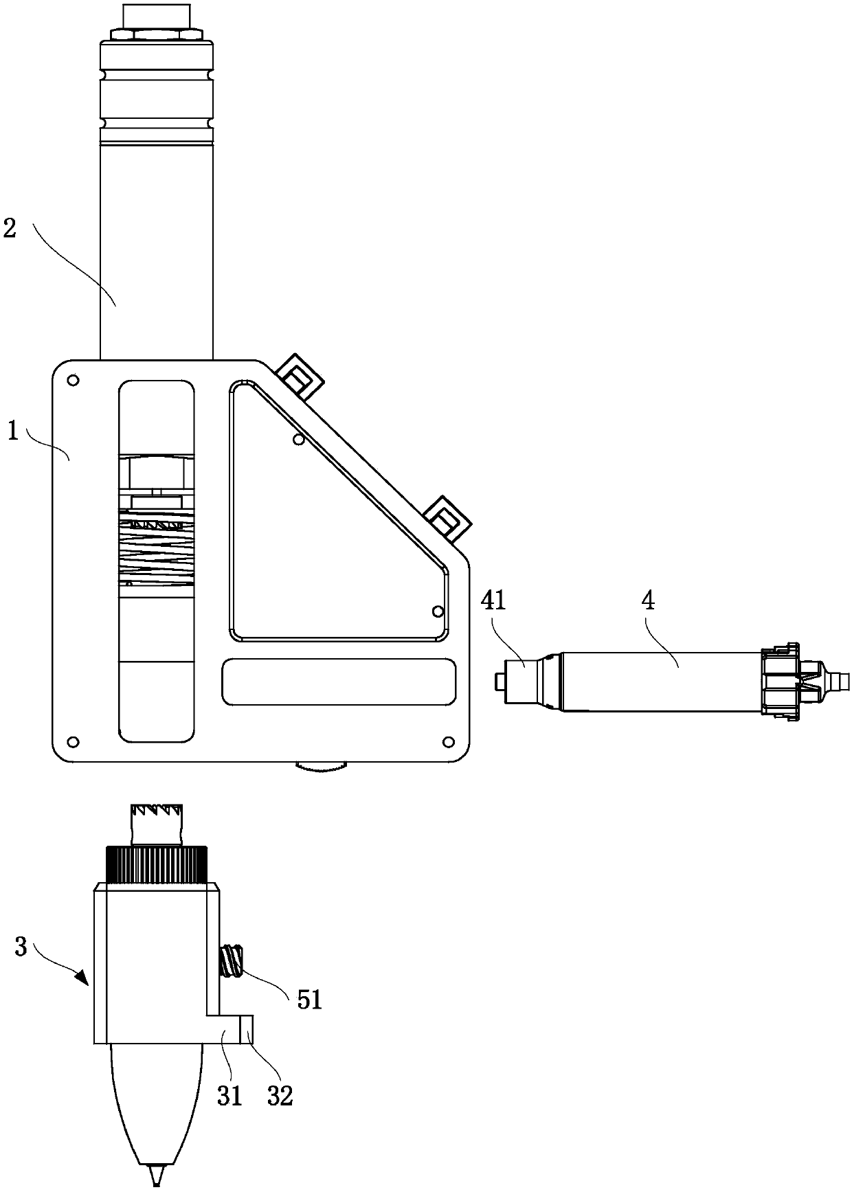
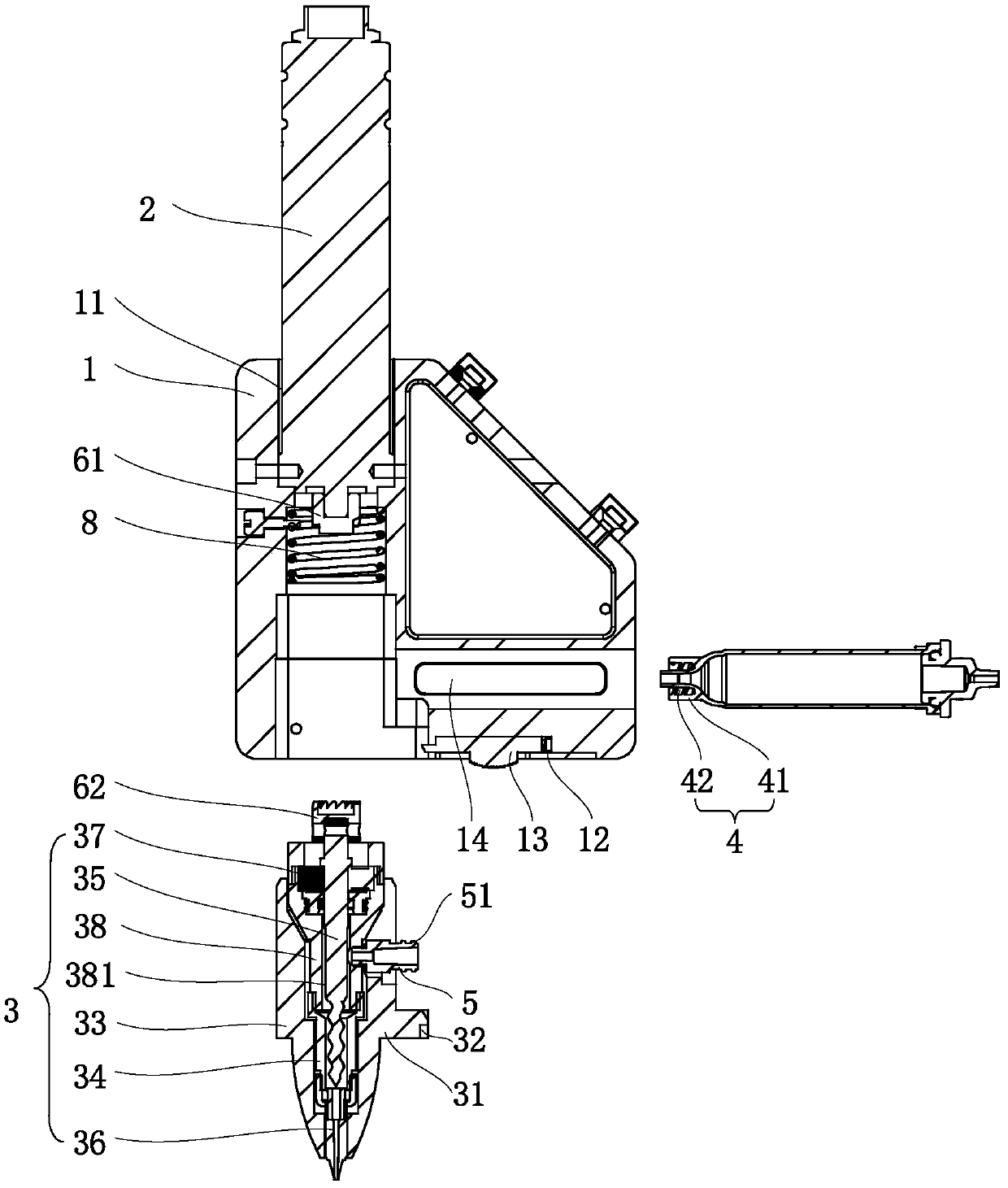
[0048] see Figure 1 to Figure 3 , the embodiment of the present invention provides a print nozzle, including a casing 1 , a driving part 2 and a screw pump assembly 3 . The casing 1 includes a mounting hole 11 , the driving component 2 is mounted on one end of the mounting hole 11 , and the screw pump assembly 3 is mounted on the other end of the mounting hole 11 . The end of the drive shaft of the drive part 2 and the end of the rotor 35 of the screw pump assembly 3 form a fit that can drive and rotate, but does not form constraints in the disassembly direction, so that the drive part 2 can drive the rotor 35 to rotate without affecting the screw. Disassembly of pump assembly 3.

[0049] In some embodiments, the disassembly direction refers to a direction parallel to the axial direction of the rotor 35 of the screw pump assembly 3 and away fro...


PUM


Abstract

The invention discloses a printing nozzle, and relates to the field of biological printing. The printing nozzle is used for achieving tool-free dismounting of a screw pump. The printing nozzle comprises a housing, a driving part and a screw pump assembly, wherein the housing comprises a mounting hole, and the driving part is mounted at one end of the mounting hole; the screw pump assembly is mounted at the other end of the mounting hole; and the end of a driving shaft of the driving part and the end of a rotor of the screw pump assembly form cooperation which can be driven to rotate and is unconstrained in the dismounting direction of the screw pump assembly. According to the technical scheme, constraints between the driving part and the screw pump assembly are reduced, and the cooperationof the driving part and the screw pump assembly only needs to enable the driving part and the screw pump assembly to rotate synchronously. Due to the fact that no extra and unnecessary constraints exist between the driving part and the screw pump assembly, when the screw pump needs to be cleaned and replaced and the screw pump assembly needs to be dismounted and mounted, the needed removed constraints are few, and dismounting and mounting are convenient, fast and efficient.

Description

technical field [0001] The invention relates to the field of biological printing, in particular to a printing nozzle. Background technique [0002] Bio-3D printing refers to the printing of biological materials (including natural biological materials, synthetic biological materials or cell solutions) into designed three-dimensional structures through the principles and methods of 3D printing. Different from ordinary 3D printing technology, the biological tissues or organs produced by bio-3D printing technology have certain biological functions, which need to provide conditions for the further growth of cells and tissues. It is precisely because of the above characteristics that bio-3D printing technology is facing many specific technical problems in the development. [0003] Among them, in the field of biological 3D printing, the technology of using cells as printing materials is called cell 3D printing technology. People can use cells and biocompatible materials to make bi...

Claims


Application Information

Patent Timeline
Patent Type & Authority Applications(China)
IPC IPC(8): B29C64/209B29C64/393C12M1/00B33Y30/00B33Y50/02
CPCB29C64/209B29C64/393B33Y30/00B33Y50/02C12M1/00
Inventor 蒋智何峻轩李意军
Owner SICHUAN REVOTEK CO LTD
Learn More