A space building cavity ventilation and lighting structure

A technology for building structures and cavities, which is applied to building components, building structures, buildings, etc., can solve the problems of unfavorable building lighting, poor ventilation effect, and failure to realize rainwater recycling, so as to improve ventilation and lighting effects, improve The effect of light and airy effects

Active Publication Date: 2020-03-27
SHENYANG JIANZHU UNIVERSITY
View PDF5 Cites 0 Cited by
  • Summary
  • Abstract
  • Description
  • Claims
  • Application Information

AI Technical Summary

Problems solved by technology

[0003] as attached figure 1 In the ventilation structure of the building shown, a central centralized ventilation cavity or a double-sided long ventilation cavity is set in the building. The problems caused by this scheme are very obvious, the ventilation effect is not good, and it is not conducive to the lighting of the building , but also can not achieve rainwater recycling

Method used


Image

  • A space building cavity ventilation and lighting structure
  • A space building cavity ventilation and lighting structure
  • A space building cavity ventilation and lighting structure

Examples


Embodiment 1

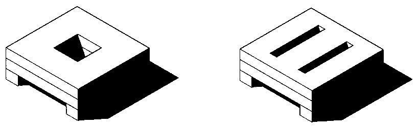
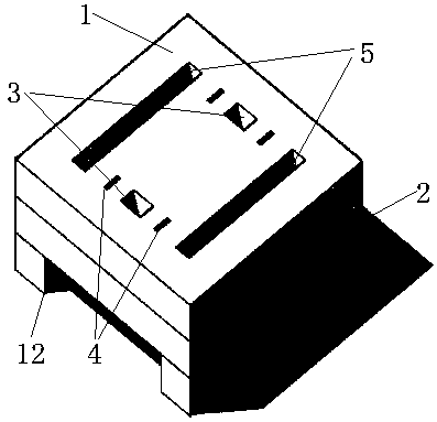
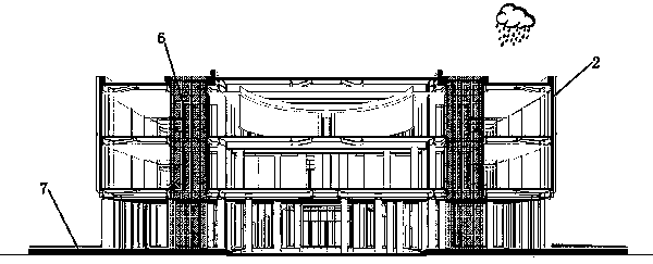
[0024] Please refer to the attached Figure 2 to Figure 4 , the purpose of this embodiment is to provide a space building cavity ventilation and lighting structure, including: a space building structure main body 1 and a ventilation and lighting cavity; the space building structure main body 1 has a plurality of floors 2, and a plurality of floors 2 are provided with Multiple ventilation and lighting cavities; multiple ventilation and lighting cavities are composed of interconnected horizontal cavities 12 and multiple sets of vertical cavities, and the horizontal cavities 12 are set and run through the bottom of the space building structure main body 1; multiple sets of vertical cavities The main body 1 of the space building structure is connected up and down, and each group of vertical cavities is arranged symmetrically. Multiple groups of vertical cavities are surrounded by a rectangular distribution. Lighting effects.

[0025] Specifically, the multiple ventilation and lig...

Embodiment 2

[0028] The plurality of ventilation and lighting cavities include a first group of vertical cavities 3, a second group of vertical cavities 4 and a third group of vertical cavities 5, and the cavities of each group of vertical cavities are elongated cavities with the same shape. The first group of vertical cavities 3 , the second group of vertical cavities 4 and the third group of vertical cavities 5 are sequentially arranged from the center of the space building structure main body 1 to the outside. The cross-sectional area of ​​the first group of vertical chambers 3 is larger than that of the second group of vertical chambers 4 , and the cross-sectional area of ​​the third group of vertical chambers 5 is larger than that of the first group of vertical ventilation chambers 3 . The two vertical cavities of the first group of vertical cavities 3 are symmetrically arranged between the two elongated cavities of the third group of vertical cavities 5, and the first to four elongate...


PUM


Abstract

The invention relates to the technical field of buildings, in particular to a space building cavity ventilation and lighting structure. The structure comprises a space building structure main body andventilation lighting cavities, wherein the space building structure main body is provided with a plurality of floors, the plurality of ventilation lighting cavities are arranged on the plurality of floors, the plurality of ventilation lighting cavities are composed of horizontal cavities communicating with one another and a plurality of sets of vertical cavities, the horizontal cavities are formed in the bottom of the space building structure main body in a penetrating mode, the plurality of sets of vertical cavities penetrate through the space building structure main body up and down, each set of vertical cavities are symmetrically arranged, the plurality of sets of vertical cavities enclose to be distributed in a rectangular mode, and the ventilation lighting cavities are used for guiding passing of wind and illumination of light.

Description

technical field [0001] The invention relates to the technical field of buildings, and more specifically relates to a space building cavity ventilation and daylighting structure. Background technique [0002] High-rise buildings are usually equipped with an internal ventilation system. The function of the ventilation system is to promote the exchange and circulation of the air in the building and the outside air to meet the needs of the indoor personnel to engage in various activities. At present, the more commonly used scheme of the ventilation system is to add ventilation windows on the building, specifically adding windows on the outer wall of each floor of the building, adding ventilation skylights on the top of the building, and adding ventilation channels or pipelines in the building. Increase indoor and outdoor air convection. [0003] as attached figure 1 In the ventilation structure of the building shown, a central centralized ventilation cavity or a double-sided l...

Claims


Application Information

Patent Timeline
Patent Type & Authority Patents(China)
IPC IPC(8): E04B1/00E04B7/18E04F17/04E04F17/06E03F1/00
CPCE03F1/002E04B1/00E04B7/18E04B2001/0053E04F17/04E04F17/06
Inventor 张伶伶张帆焦洋赵伟峰李强
Owner SHENYANG JIANZHU UNIVERSITY
Why Eureka
Try Eureka