Double-drive electric carrying equipment

An electric and equipment technology, used in electric vehicles, hospital equipment, control drives, etc., can solve problems such as no power assistance, only synchronous rotation, and consumption.

Pending Publication Date: 2020-01-31
佛山市源远自动化设备科技有限公司
View PDF0 Cites 1 Cited by
  • Summary
  • Abstract
  • Description
  • Claims
  • Application Information

AI Technical Summary

Problems solved by technology

Therefore, when the medical transfer bed is loaded with people, it is more laborious to push the medical transfer bed, and it is difficult to control the direction of walking when operated by one person.
In addition, because patients with limited mobility often need to do more examinations during hospitalization, and different testing items are located in different areas, existing hospitals generally need to arrange two nurses (or arrange one nurse and require the patient's family to accompany them) Transferring patients to different testing areas for testing through medical transfer beds consumes a lot of manpower and increases hospitalization costs
[0003] Also, take the power-assisted luggage trolley at the airport as an example. It has two power wheels. Although the two power wheels are driven by electric batteries and have the function of power assistance, the two power wheels are in a linkage state and can only rotate synchronously. Therefore, when turning a corner, the user still needs to provide a large auxiliary turning force in order to realize the steering of the luggage trolley
[0004] In addition, take a flat trolley as an example, it does not have power assistance, and it is more difficult to pull heavy objects

Method used


Image

  • Double-drive electric carrying equipment
  • Double-drive electric carrying equipment
  • Double-drive electric carrying equipment

Examples


Embodiment Construction

[0032] The present invention will be further described below in conjunction with the accompanying drawings and embodiments.

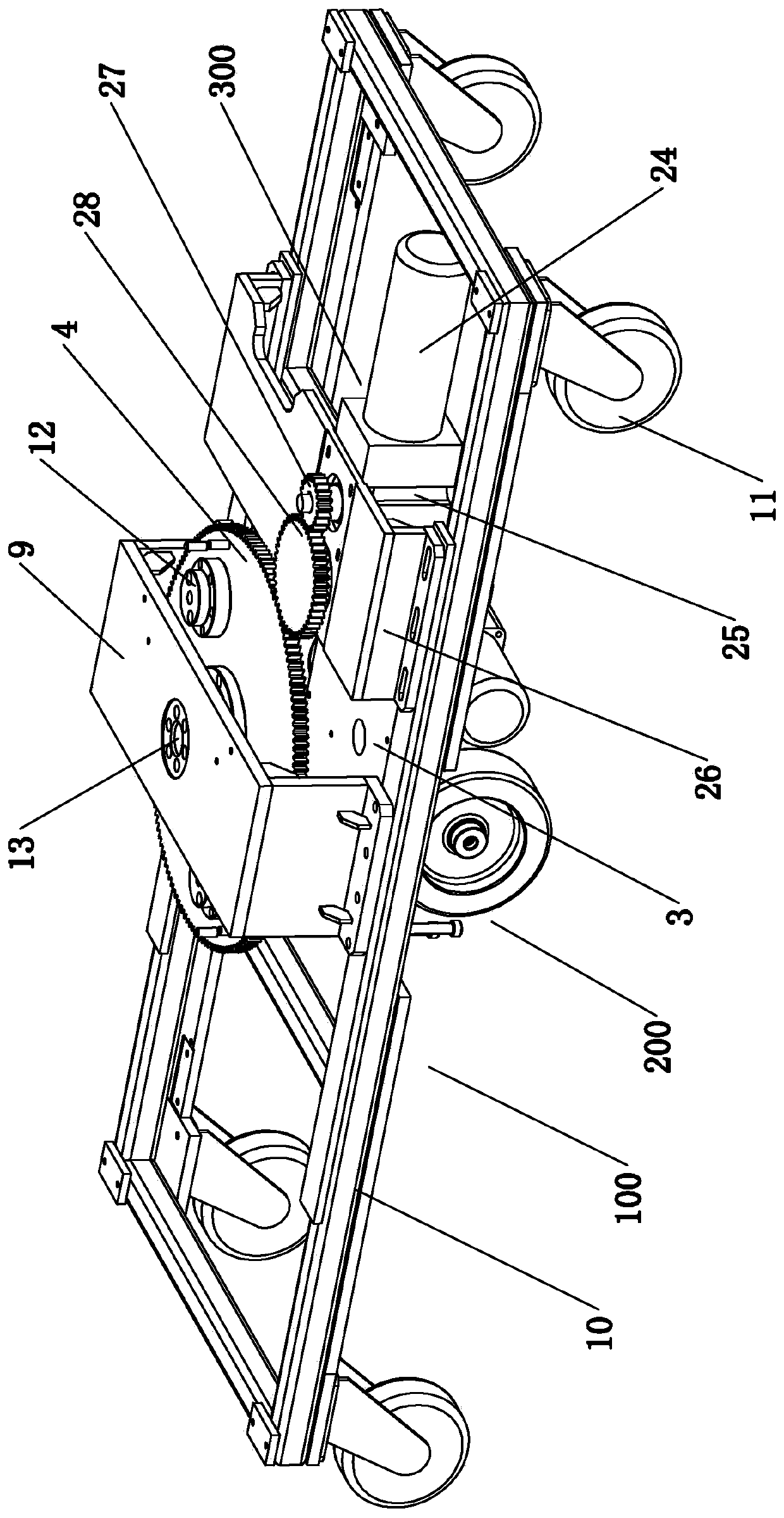
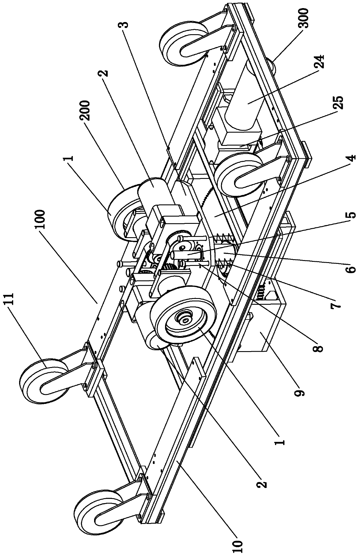
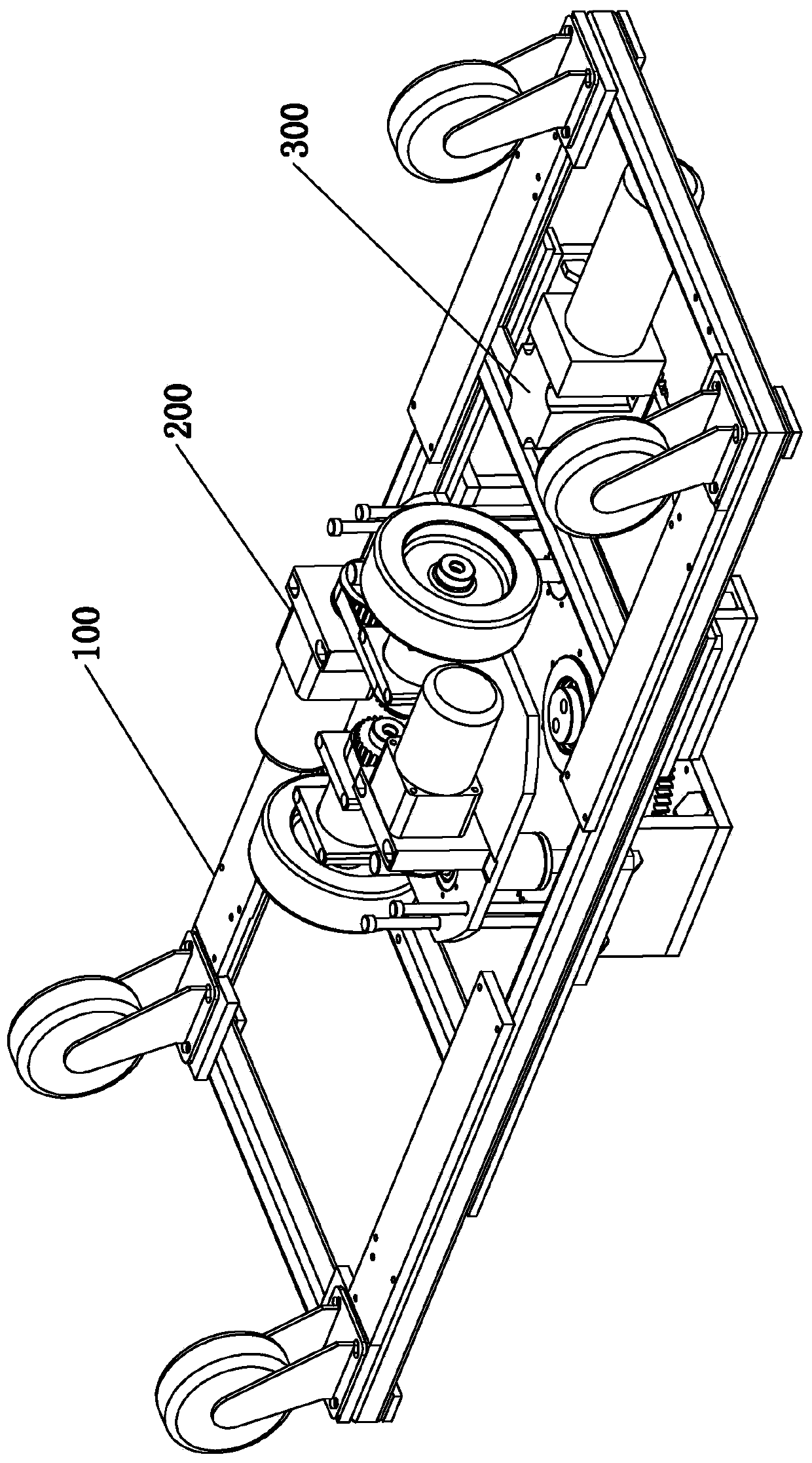
[0033] see figure 1 , figure 2 and Figure 6-Figure 10 As shown, a dual-drive electric vehicle includes a vehicle frame 100 and a power unit 200. The power unit 200 is arranged on the vehicle frame 100. The power unit 200 includes two sets of travel drive mechanisms. The travel drive mechanism includes drive wheels 1 and Walking drive motor 2, the driving wheels 1 of two sets of walking driving mechanisms are located at the bottom of the vehicle frame 100, and are distributed on one left and one right, and the driving wheels 1 are connected with the driving drive motor 2 in transmission.

[0034] The axes of the drive wheels 1 of the two sets of travel drive mechanisms are located on the same straight line. The walking drive motor 2 is a servo motor.

[0035] The power device 200 also includes a wheel frame 3, which is directly or indirectly connec...


PUM


Abstract

The invention relates to double-drive electric carrying equipment which comprises a frame, a power device, a main control circuit and a battery. The power device, the main control circuit and the battery are arranged on the frame, the power device comprises two sets of walking driving mechanisms, the walking driving mechanisms comprise driving wheels and walking driving motors, the driving wheelsof the two sets of walking driving mechanisms are positioned at the bottom of the frame and distributed from left to right, and the driving wheels are in transmission connection with the walking driving motors; and the main control circuit is electrically connected with the battery, and the walking driving motors of the two sets of walking driving mechanisms are respectively electrically connectedwith the main control circuit. The double-drive electric carrying equipment is driven by the power device and is more labor-saving, and the two driving wheels of the power device are each controlledby one walking driving motor, so that the two driving wheels can be independently controlled, and when the two driving wheels are synchronous, a linear driving frame can be realized; and when the twodriving wheels operate differentially, steering and walking of the vehicle frame can be realized.

Description

technical field [0001] The invention relates to a vehicle, in particular to a dual-drive electric vehicle. Background technique [0002] The current vehicles include trolleys, medical transfer beds, etc. Taking the medical transfer bed as an example, it mainly includes a lower bed frame, an upper bed frame and swivel casters. The swivel casters are set at the bottom of the lower bed frame, and the upper bed frame is set above the lower bed frame. The upper bed frame is mainly used for placing mattresses and lying down for patients, and the lower bed frame can be used for placing medical instruments and equipment. Therefore, when the medical and nursing transfer bed is loaded with people, it is difficult to push the medical and nursing transfer bed, and it is difficult to control the walking direction of the operation by one person. In addition, because patients with limited mobility often need to do more examinations during hospitalization, and different testing items are l...

Claims


Application Information

Patent Timeline
Patent Type & Authority Applications(China)
IPC IPC(8): B62D11/04B60L15/20A61G7/05
CPCA61G7/05A61G7/0528B60L15/20B60L2200/30B62D11/04Y02T10/72
Inventor 吕鸿钧林尚雷黄乐军吕鸿雁黄勇军
Owner 佛山市源远自动化设备科技有限公司
Why Eureka
Try Eureka